
Page 92 - Mechanics Analysis Composite Materials
P. 92
Chapter 3. Mechanics of a unidirectional ply 77
0 5 10 15 20 25 30 35 40 45 50
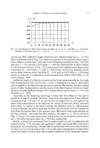
Fig. 3.22. Distribution of shear stresses along the fibers for k =4, Ef = 250 GPa, G,,, = 0.125 GPa.
Numbers of the matrix layers: (- - - -) n = 1; (.......) n = 2; (-- --) n = 3; (--- -) n = 4.
increase the fiber ineffectivelength which becomes infinitely large for G, ---f 0. This
effect is demonstrated in Fig. 3.21 which corresponds to the material whose matrix
shear stiffness is much lower than that in the foregoing example (see Fig. 3.19). For
this case, I, = 50, and Eq. (3.57) yields Zi = 0.8 mm. Distribution of shear stresses
in this material is shown in Fig. 3.22. Experiments with unidirectional glass-epoxy
composites (Et-= 86.8 GPa, uy = 0.68, a = 0.015) have shown that reduction of the
matrix shear modulus from 1.08 GPa (2; = 0.14 mm) to 0.037 GPa (Z; = 0.78 mm)
results in reduction of longitudinal tensile strength from 2010 to 1290 MPa, Le., by
35.8% (Chiao, 1979).
Ineffective length of a fiber in a matrix can be found experimentally by the single
fiber fragmentation test. For this test, a fiber is embedded in a matrix, and tensile
load is applied to the fiber through the matrix until the fiber brakes. Further loading
results in fiber fragmentation, and the length of the fiber fragment which no longer
brakes is the fiber ineffective length. For a carbon fiber in epoxy matrix, l; = 0.3 mm
(Fukuda et al., 1993).
According to the foregoing reasoning, it looks like the stiffness of the matrix
should be as high as possible. However, there exists the upper limit of this stiffness.
Comparing Figs. 3.20 and 3.22 we can see that the higher the Gn,,the higher is the
shear stress concentration in the matrix in the vicinity of the crack. If the maximum
shear stress, z",, acting in the matrix reaches the ultimate value, i,, delamination
will occur between the matrix layer and the fiber, and the matrix will not transfer the
load from the broken fiber to the adjacent ones. Maximum shear stress depends on
the fiber stiffness - the lower the fiber modulus, the higher is z,. This is shown in
Figs. 3.23 and 3.24, where shear stress distributions are presented for aramid fibers
(Ef = 150 GPa) and glass fibers (Ef = 90 GPa), respectively.
Finally, it should be emphasized that the plane model of a ply, considered in this
section (see Fig. 3.15), provides only qualitative results concerning fibers and matrix
interaction. In real materials, a broken fiber is surrounded with more than two fibers
(at least 5 or 6 as can be seen in Fig. 3.2), so the stress concentration in these fibers
and in the matrix is much lower than would be predicted by the foregoing analysis.