
Page 128 - Mechanics of Asphalt Microstructure and Micromechanics
P. 128
120 Ch a p t e r F o u r
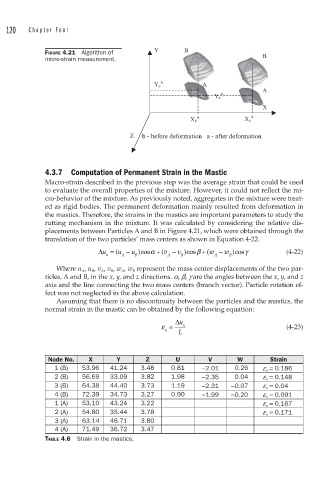
FIGURE 4.21 Algorithm of
micro-strain measurement.
4.3.7 Computation of Permanent Strain in the Mastic
Macro-strain described in the previous step was the average strain that could be used
to evaluate the overall properties of the mixture. However, it could not reflect the mi-
cro-behavior of the mixture. As previously noted, aggregates in the mixture were treat-
ed as rigid bodies. The permanent deformation mainly resulted from deformation in
the mastics. Therefore, the strains in the mastics are important parameters to study the
rutting mechanism in the mixture. It was calculated by considering the relative dis-
placements between Particles A and B in Figure 4.21, which were obtained through the
translation of the two particles’ mass centers as shown in Equation 4-22.
Δu = ( u − u )cosα + ( v − v )cosβ + ( w − w )cosγ (4-22)
n A B A B A B
Where u A , u B , v A , v B , w A , w B represent the mass center displacements of the two par-
ticles, A and B, in the x, y, and z directions. a, b, g are the angles between the x, y, and z
axis and the line connecting the two mass centers (branch vector). Particle rotation ef-
fect was not neglected in the above calculation.
Assuming that there is no discontinuity between the particles and the mastics, the
normal strain in the mastic can be obtained by the following equation:
Δ u
ε = n (4-23)
n L
Node No. X Y Z U V W Strain
1 (B) 53.96 41.24 3.48 0.81 −2.01 0.26 e n = 0.186
2 (B) 56.69 33.09 3.82 1.98 −2.35 0.04 e n = 0.148
3 (B) 64.38 44.40 3.73 1.19 −2.31 −0.07 e n = 0.04
4 (B) 72.39 34.73 3.27 0.90 −1.99 −0.20 e n = 0.091
1 (A) 53.10 43.24 3.22 e n = 0.167
2 (A) 54.80 35.44 3.78 e n = 0.171
3 (A) 63.14 46.71 3.80
4 (A) 71.49 36.72 3.47
TABLE 4.6 Strain in the mastics.