
Page 129 - Mechanics of Asphalt Microstructure and Micromechanics
P. 129
Experimental Methods to Characterize the Heterogeneous Strain F ield 121
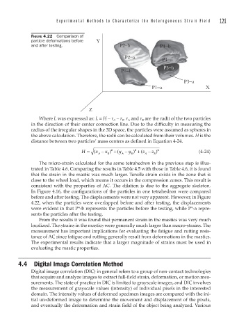
FIGURE 4.22 Comparison of
particle deformations before Y
and after testing. P2−b P4−b
P2−a P4−a
P3−b
P1−b
P3−a
P1−a X
Z
Where L was expressed as: L = H − r A − r B . r A and r B are the radii of the two particles
in the direction of their center connection line. Due to the difficulty in measuring the
radius of the irregular shapes in the 3D space, the particles were assumed as spheres in
the above calculation. Therefore, the radii can be calculated from their volumes. H is the
distance between two particles’ mass centers as defined in Equation 4-24.
2
2
H ( x − x ) + y ( − y ) + z ( − z ) 2 (4-24)
A B A B A B
The micro-strain calculated for the same tetrahedron in the previous step is illus-
trated in Table 4.6. Comparing the results in Table 4.5 with those in Table 4.6, it is found
that the strain in the mastic was much larger. Tensile strain exists in the zone that is
close to the wheel load, which means it occurs in the compression zones. This result is
consistent with the properties of AC. The dilation is due to the aggregate skeleton.
In Figure 4.16, the configurations of the particles in one tetrahedron were compared
before and after testing. The displacements were not very apparent. However, in Figure
4.22, when the particles were overlapped before and after testing, the displacements
were evident in that P*-b represents the particles before the testing, while P*-a repre-
sents the particles after the testing.
From the results it was found that permanent strain in the mastics was very much
localized. The strains in the mastics were generally much larger than macro-strains. The
measurement has important implications for evaluating the fatigue and rutting resis-
tance of AC since fatigue and rutting generally result from deformations in the mastics.
The experimental results indicate that a larger magnitude of strains must be used in
evaluating the mastic properties.
4.4 Digital Image Correlation Method
Digital image correlation (DIC) in general refers to a group of non-contact technologies
that acquire and analyze images to extract full-field strain, deformation, or motion mea-
surements. The state of practice in DIC is limited to grayscale images, and DIC involves
the measurement of grayscale values (intensity) of individual pixels in the interested
domain. The intensity values of deformed specimen images are compared with the ini-
tial un-deformed image to determine the movement and displacement of the pixels,
and eventually the deformation and strain field of the object being analyzed. Various