
Page 20 - Mechanics of Asphalt Microstructure and Micromechanics
P. 20
Introduction and Fundamentals for Mathematics and Continuum Mechanics 13
1.6.2 Description of Kinematics-Deformation Gradient and Finite Strain Tensor
1.6.2.1 Coordinate Representation
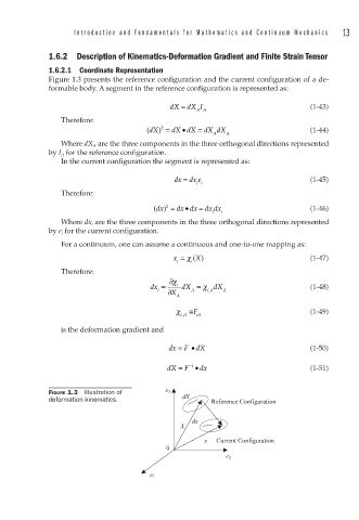
Figure 1.3 presents the reference configuration and the current configuration of a de-
formable body. A segment in the reference configuration is represented as:
dX = dX I (1-43)
AA
Therefore:
•
2
(dX ) = dX dX = dX dX (1-44)
A A
Where dX A are the three components in the three orthogonal directions represented
by I A for the reference configuration.
In the current configuration the segment is represented as:
dx = dx e (1-45)
ii
Therefore:
•
2
(dx = dx dx = dx dx (1-46)
)
i i
Where dx i are the three components in the three orthogonal directions represented
by e i for the current configuration.
For a continuum, one can assume a continuous and one-to-one mapping as:
x = χ () (1-47)
X
i i
Therefore:
∂χ
dx = i dX = χ dX (1-48)
i ∂ X A i A A
,
A
χ ≡ F (1-49)
,
iA iA
is the deformation gradient and
dx = F • dX (1-50)
−1
dX = F • dx (1-51)
FIGURE 1.3 Illustration of e 3
deformation kinematics. dX Reference Configuration
dx
X
x Current Configuration
0
e 2
e 1