
Page 263 - Mechanics of Asphalt Microstructure and Micromechanics
P. 263
F inite Element Method and Boundar y Element Method 255
Y
K
B
C
A
n t
α
O o ′ X
(a)
n s
4 3 4 3
r
o ′′
1
2
o ′ t 1 2
(b)
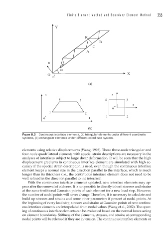
FIGURE 8.3 Continuous interface elements, (a) triangular elements under different coordinate
systems, (b) rectangular elements under different coordinate system.
elements using relative displacements (Wang, 1998). Those three-node triangular and
four-node quadrilateral elements with special strain descriptions are necessary in the
analyses of interfaces subject to large shear deformation. It will be seen that the high
displacement gradients in continuous interface element are simulated with high ac-
curacy if the special strain description is used, even though the continuous interface
element keeps a normal size in the direction parallel to the interface, which is much
longer than its thickness (i.e., the continuous interface element does not need to be
well refined in the direction parallel to the interface).
With the continuous interface elements updated, new interface elements may ap-
pear after the removal of old ones. It is not possible to directly inherit stresses and strains
at the same traditional Gaussian points of each element for a new load step. However,
the number of nodal points will never change. Therefore, it is necessary to calculate and
build up stresses and strains and some other parameters if present at nodal points. At
the beginning of every load step, stresses and strains at Gaussian points of new continu-
ous interface elements are interpolated from nodal values (Wang et al., 2002). The open-
ing of continuous interface elements can be evaluated based on the normal forces acting
on element boundaries. Stiffness of the elements, stresses, and strains at corresponding
nodal points will be released if they are in tension. The continuous interface elements or