Page 266 - Mechanics of Asphalt Microstructure and Micromechanics
P. 266

258   Ch a p t e r  E i gh t


              larger deformation, as shown in Figure 8.4b. The number of nodal points for an inter-
              face element varies and is dependent on the locations of the nodal points. The continu-
              ous interface elements are re-formed after converged results are obtained at each load
              step with node coordinates updated in the wake of each global equilibrium iteration.
              Extra equilibrium iterations are performed before a new load increment is applied for
              the new interface elements. Due to the continuous updates of the interface elements,
              stresses, strains, and other state variables at each nodal point should be tracked down.
              Initial stresses, strains, etc. at Gaussian points within a new interface element will be
              obtained by interpolating from those nodal values at the beginning of each load step
              (Wang et al., 2002).
                 After the formation of the continuous interface elements, the strains need to be for-
              mulated for triangular and rectangular interface elements, respectively. For large defor-
              mation analyses of interfaces or joints, triangular and quadrilateral interface elements
              are necessary, but not well documented. No considerable attention has been paid to
              characterize their strain distributions. In the next subsection, strains in the triangular
              and quadrilateral interface elements are defined and derived. The discussions in the
              previous section are fundamentals to the new strain descriptions. Shear and normal
              strains across interfaces are related to relative displacements between the upper and
              lower surfaces. The strains stated above are assumed to be uniform in the directions
              normal to an interface.

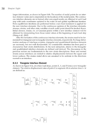
              8.3.3  Triangular Interface Element
              As shown in Figure 8.3a, at certain load steps, points K, A, and B form a new triangular
              element. The relative displacement rates of point K to segment AB at solution time t+ Δt
              are defined as:
                                                                      +
                                                                      t+Δt  •
                                                                        ⎧   ⎫
                                                                        ⎪ U  A ⎪
                       t+Δ t     t+Δ t                                  ⎪  • ⎪
                         ⎧  •  ⎫    ⎧  •  ⎫
                         ⎪Δ W t ⎪   ⎪ U K ⎪ ⎡  + t Δ t N  C  0  + t Δ t N C  0  ⎤  ⎪V  A  ⎪
                                         −
                         ⎨  •  ⎬ =  ⎨  •  ⎬ − ⎢  A  + t Δ t  C  B  + t Δ t  C  ⎥  ⎨  •  ⎬
                                        ⎪ ⎣ ⎢
                         ⎪ Δ W n ⎭  ⎪ V K ⎭  0      N  A   0      N B  ⎦ ⎥  ⎪ ⎪ U  B ⎪
                              ⎪
                                    ⎩
                         ⎩
                                                                            ⎪
                                                                        ⎪  •  ⎪
                                                                        ⎩ V B  ⎭
                                                                       + t Δ t
                                                                          ⎡  •  ⎤ ⎤
                                                                          ⎢ U  A ⎥
                                                                          ⎢ • ⎥
                                                                          ⎢V ⎥   (8-48)
                                                                            A
                                                                          ⎢ • ⎥
                                  − ⎡  + t Δ t N  C  0  −  + t Δ t N  C  0  1 0⎤  ⎢ U  ⎥
                                = ⎢ ⎢   A   + t Δ      B    + t Δ     ⎥   ⎢  B ⎥
                                  ⎣ ⎢  0  −  t N  C A  0  −  t N  C B  0 1 ⎥ ⎦  ⎢  •  ⎥
                                                                          ⎢ V  B ⎥
                                                                          ⎢  •  ⎥
                                                                          ⎢ U ⎥
                                                                            K
                                                                          ⎢ • ⎥
                                                                            K ⎥
                                                                          ⎢V ⎦
                                                                          ⎣

                                          + t Δ t ⎧ ⎫
                                             •
                                =  + t Δ t  ⎡N int  ⎤ ⎦  ⎨ ⎬
                                             U
                                    ⎣
                                            ⎩ ⎭
   261   262   263   264   265   266   267   268   269   270   271