Page 269 - Mechanics of Asphalt Microstructure and Micromechanics
P. 269

F inite Element Method and Boundar y Element Method   261


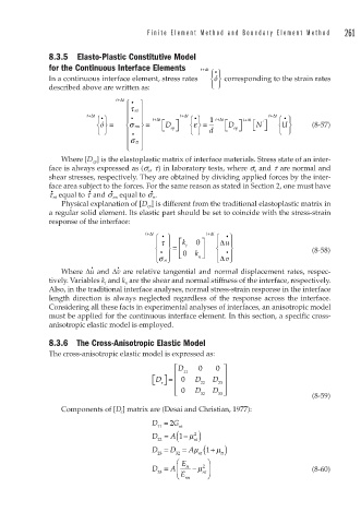
              8.3.5 Elasto-Plastic Constitutive Model
              for the Continuous Interface Elements  t+Δ t ⎧ ⎫
                                                        •
              In a continuous interface element, stress rates   ⎨ ⎬  corresponding to the strain rates
                                                        ó
              described above are written as:          ⎩ ⎭
                               t+Δ t
                                 ⎧  •  ⎫
                                 ⎪ τ nt ⎪
                       t+Δ t       • ⎪          + t Δ t               t+Δ t
                          ⎧ ⎫    ⎪   ⎪   + t Δ t  ⎧ ⎫  1  + t Δ t  t t+Δ t  ⎧ ⎫
                                     ⎪
                           •
                                                                          •
                                                   •
                           ó ⎨ ⎬ =  ⎨ σ nn ⎬ =  ⎡ D  ⎤  ⎨ ⎬ =  ⎡ D  ⎤  ⎡ ⎣ N ⎤ ⎦  ⎨ U ⎬  (8-57)
                                                   ε
                                                                     '
                          ⎩ ⎭    ⎪  • ⎪    ⎣  ep ⎦  ⎩ ⎭  d  ⎣  ep ⎦      ⎩ ⎭
                                 ⎪σ tt ⎪
                                 ⎩ ⎪  ⎭ ⎭ ⎪
                 Where [D ep ] is the elastoplastic matrix of interface materials. Stress state of an inter-
              face is always expressed as (s n , t) in laboratory tests, where s n  and t are normal and
              shear stresses, respectively. They are obtained by dividing applied forces by the inter-
              face area subject to the forces. For the same reason as stated in Section 2, one must have
                                        •
                             •
                        •
              •
              t nt  equal to t  and s nn  equal to s n .
                 Physical explanation of [D ep ] is different from the traditional elastoplastic matrix in
              a regular solid element. Its elastic part should be set to coincide with the stress-strain
              response of the interface:
                                      t+Δ t           t+Δ t
                                         ⎧  •  ⎫         ⎧  • ⎫
                                         ⎪ τ  ⎪  k ⎡  0  ⎤  ⎪ Δ u⎪
                                         ⎨  •  ⎬ = ⎢  t  ⎥  ⎨ ⎨  •  ⎬            (8-58)
                                         ⎪ σ n ⎭ ⎪  ⎣  0  k n⎦  ⎪ Δ v ⎭ ⎪
                                         ⎩               ⎩
                        •      •
                 Where Δu and Δv are relative tangential and normal displacement rates, respec-
              tively. Variables k t  and k n  are the shear and normal stiffness of the interface, respectively.
              Also, in the traditional interface analyses, normal stress-strain response in the interface
              length direction is always neglected regardless of the response across the interface.
              Considering all these facts in experimental analyses of interfaces, an anisotropic model
              must be applied for the continuous interface element. In this section, a specific cross-
              anisotropic elastic model is employed.
              8.3.6  The Cross-Anisotropic Elastic Model
              The cross-anisotropic elastic model is expressed as:
                                              ⎡ D 11  0  0  ⎤
                                        ⎡ ⎣ D ⎤ =  ⎢ ⎢  0  D 22  D 23 ⎥ ⎥
                                          e ⎦
                                              ⎣
                                              ⎢ 0  D    D ⎥ ⎦
                                                     32  33                      (8-59)
                 Components of [D e ] matrix are (Desai and Christian, 1977):
                                        D =  2 G nt
                                          11
                                        D = (     μ 2
                                             A 1− )
                                          22       nt
                                                  A (
                                        D =  D = μ    1+ μ tt )
                                          23  32    nt
                                              ⎛ E     ⎞
                                           =
                                        D = A ⎜  tt  − μ 2 ⎟                     (8-60)
                                          33  ⎝ E    nt ⎠
                                                 nn
   264   265   266   267   268   269   270   271   272   273   274