
Page 265 - Mechanics of Asphalt Microstructure and Micromechanics
P. 265
F inite Element Method and Boundar y Element Method 257
Normal solid elements
Distorted interface or joint elements
(a)
Renewed interface or joint elements
K A B
M N L P Q C D
Lower boundary S JI Upper boundary S IJ
(b)
K
A B
α β
α β
M N D
C
(c) (d)
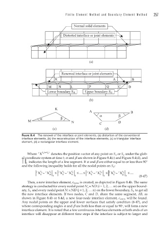
FIGURE 8.4 The renewal of the interface or joint elements, (a) distortion of the conventional
interface elements, (b) the reconstruction of the interface elements, (c) a triangular interface
element, (d) a rectangular interface element.
t
Where X S IJ ( orS JI ) denotes the position vector of any point on S IJ or S JI under the glob-
al coordinate system at time t; a and b are shown in Figure 8.4(c) and Figure 8.4(d), and
indicates the length of a line segment. If a and b are either equal to or less than 90°
2
and the following inequality holds for all the nodal points on S JI :
X − X ≤ X − X ≤ .... ≤ X − X ≤ X − X ≤ ....
t S IJ t S JI t S IJ t S JI t S IJ t S JII t S IJ t S JI
X
K M 2 K N 2 K P 2 K Q 2 (8-47)
Then, a new interface element, e KMN , is created, as depicted in Figure 8.4b. The same
i
strategy is conducted for every nodal point N u ∈ND (i = 1, 2, … m) on the upper bound-
ary, S IJ, and every nodal point N i ∈ND (j = 1, 2, … n) on the lower boundary, S JI, to get all
j
the new interface elements. If two nodes, C and D, share the same segment, AB, as
shown in Figure 8.4b or 8.4d, a new four-node interface element, e ABCD, will be found.
Any nodal points on the upper and lower surfaces that satisfy condition (8-47), and
o
where corresponding angles a and b are both less than or equal to 90 , will form a new
interface element. It is noted that a few continuous interface elements at both ends of an
interface will disappear at different time steps if the interface is subject to larger and