Page 397 - Mechanics of Asphalt Microstructure and Micromechanics
P. 397
Simulation of  Asphalt Compaction   389


              measured information to adapt the equipment performance continuously to the required
              conditions. This system controls the different compaction parameters of the roller: am-
              plitude, frequency, and working speed (impact distance). The modulus measurements
              are made by the instrumented roller itself. The system is pre-conditioned with the range
              of acceptable modulus values (target value) and automatically adjusts the roller settings
              to achieve the target modulus if the readings are not within tolerance.
                 A dynamic compactor produces nonlinear oscillations whose characteristic proper-
              ties can be described analytically using a theoretical model of the interaction between a
              vibratory roller and the ground. The soil-drum-interaction-force (F B ) is defined as fol-
              lows in Equation 11-20 (Anderegg, 2000).
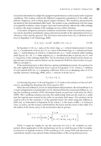
                                 F ≅− m x +  m r Ω cos( Ω t +) ( m +  m ⋅)  g   (11-20)
                                                 ⋅
                                                2
                                        ¨
                                  B    d  d  u u            t  d
                 In Equation 11-20, m d  = mass of the drum (kg), x d  = vertical displacement of drum
                                           2
              (m),  ˙˙ x d  = acceleration of drum (m/s ), m f  = mass of the frame (kg), m u  = unbalanced mass
              (kg), r u  = radial distance at which m u  is attached (m), m u r u  = static moment of the rotating
              shaft (kg·m), Ω = 2π · f, t = time elapsed (s), g = acceleration due to gravity (m/s ), and
                                                                                 2
              f = frequency of the rotating shaft (Hz). The acceleration of the drum and the phase an-
              gle between excitation and oscillation can be measured. With this information, it is pos-
              sible to calculate F B .
                 If the underlying layer is described as a spring and dashpot system, the equation for
              the soil/asphalt-drum interaction force is given in Equation 11-21, where k B  = stiffness
              of soil/asphalt (kN/m), d B  = damping coefficient (kN·s/m) (a damping ratio of 0.2 is
              usually assumed, Anderegg, 2000), and ˙ x d  = velocity of drum (m/s).
                                           F ≅ k x + d x ⋅  ·                   (11-21)
                                            B   B d  B  d
                 Combining Equation 11-20 and Equation 11-21 leads to the solution of the soil stiff-
              ness k B , assuming the damping ratio to be equal to 20%.
                 Since the soil stiffness k B  is not an independent soil parameter, the soil modulus E as
              a more independent soil parameter can be obtained from the measured stiffness k B , us-
              ing the Lundberg solution (1939) developed based on previous work done by Hertz
              (1895). The Lundberg solution provides the relationship between the load on a roller
              and the imprint area created by the roller on an elastic half space. The solution can be
              used to solve for the modulus E of the material below the roller using the stiffness k B
              [MN/m], as formulated in Equation 11-22, where L is the drum width, v is Poisson’s
              ratio, m f and m d are the masses contributed by the frame and the drum of the roller, R is
              the radius of the drum, and g is the acceleration due to gravity.

                                                 EL⋅⋅π
                          k =                                                   (11-22)
                           B           ⎛         ⎡       π ⋅  3  ⋅     ⎤⎞
                                    2
                               ⋅ 21(  −υ ) ⎜  +  1  ⋅ln ⎢   LE         ⎥⎟
                                      ⋅ 2 14.
                                       ⎜ ⎝   2   ⎣  1 ( ⎢  −υ ) ⋅16 ⋅(m +  m  ) R g ⎥ ⎠ ⎟
                                                                   ⋅
                                                                     ⋅
                                                      2
                                                           (
                                                                       ⎦
                                                             f   d
                 While it might be helpful to use the estimates for soil or AC modulus as com-
              pacted, direct application of the method may not be so valid because of the viscoplas-
              tic behavior of asphalt mixtures. FEM modeling of AC using FEM and advanced vis-
              coplasticity models may present better interpretation of the compaction process.

