
Page 409 - Mechanics of Asphalt Microstructure and Micromechanics
P. 409
Characterization and Modeling Anisotropic Proper ties of Asphalt Concrete 401
True triaxial devices that have been widely used in soil mechanics have advantages for
use in the characterization of the above fundamental properties.
Different types of true triaxial devices have been developed worldwide, and they
can be classified into three categories: (1) rigid boundary (Hambley, 1969; Airey and
Wood 1988); (2) flexible boundary (Ko and Scott, 1967; Sture and Desai, 1979), and (3)
mixed boundary (Green, 1971; Lade and Duncan, 1973). The advantages and disadvan-
tages of these three types of true triaxial devices have been discussed by Sture (1979)
and Arthur (1988). The original development of the flexible boundary type of device
used in this work was presented by Atkinson (1972) for multiaxial testing of rock mate-
rials. A detailed description of the original components is presented by Atkinson (1972),
Sture (1979), and NeSmith (1997). The stress-controlled, computer-driven cubical test-
ing device consists basically of six main components or modules: (1) a frame; (2) six
wall assemblies; (3) a deformation measuring system; (4) a stress application and con-
trol system; (5) six rigid membranes; and (6) a data acquisition and process control
system (DA/PCS). A detailed and illustrated description of these components follows.
12.6.2 The Cubical Device System
12.6.2.1 Steel Frame
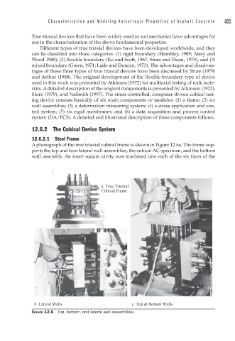
A photograph of the true triaxial cubical frame is shown in Figure 12.6a. The frame sup-
ports the top and four lateral wall assemblies, the cubical AC specimen, and the bottom
wall assembly. An inner square cavity was machined into each of the six faces of the
a. True Triaxial
Cubical Frame
b. Lateral Walls c. Top & Bottom Walls
FIGURE 12.6 Top, bottom, and lateral wall assemblies.