
Page 411 - Mechanics of Asphalt Microstructure and Micromechanics
P. 411
Characterization and Modeling Anisotropic Proper ties of Asphalt Concrete 403
12.6.2.4 Stress Application and Control System
The hydraulic pressure applied through the six rigid membranes to the top, bottom,
and lateral sides of the cubical AC specimen is generated and controlled by a computer-
driven electro-hydraulic pressure system. The fluid is pressurized by a 20-gallon stan-
dard hydraulic power unit or pump (manufactured and installed by ORTON Indus-
tries, Inc.) that can deliver a variable output pressure up to 10.35 MPa (1500 psi) on each
side of the specimen, depending on the initial setting and calibration of three computer-
driven proportional pressure relief valves (manufactured by Parker Motion & Control,
Inc.) connected to an equal number of outlet ports in the power unit (Figure 12.7). The
RE series proportional relief valves provide variable hydraulic pressure control in re-
sponse to a variable voltage or current command signal. The RE series’ valves feature
an on-board electronic driver with adjustments for the rate at which the pressure in-
creases and decreases (Figure 12.7). In addition, there are adjustments to electronically
set the minimum pressure and maximum pressure delivered to the specimen (valves’
calibration process).
For this study, the proportional pressure relief valves were calibrated to work at a
minimum pressure of 175 kPa (25 psi) and a maximum pressure of 1225 kPa (175 psi).
The output lines from the three proportional pressure relief valves split into two lines
to supply the pressures to the positive (+) and negative (–) faces of the cubical asphalt
concrete specimen for each particular loading condition. These positive and negative
faces are designated as X(+), X(–), Y(+), Y(–), accounting for the four lateral sides, and
Z(+), Z(–), accounting for the top and bottom sides. The output lines from the valves are
transmitted to the test cell by flexible hoses having a rated burst strength of 27.50 MPa
(4000 psi).
A quick-disconnect coupling between the hose and the fluid pressure inlet/outlet
connections of the wall assembly makes for easy assembly. Any principal stress combi-
nation path can be achieved by simultaneous control over the three computer-driven
proportional relief valves. The proportional relief valves receive an analog input signal
(volt) from an analog output signal-conditioning interface (IOB120-01 interface kit from
Analog Devices, Inc.) connected to the digital-to-analog converter (RTI-815 board from
Analog Devices, Inc.) plugged into the CPU of the computer. Low-viscosity Mobil-type
(DTE 26) hydraulic fluid was used as the pressurizing medium.
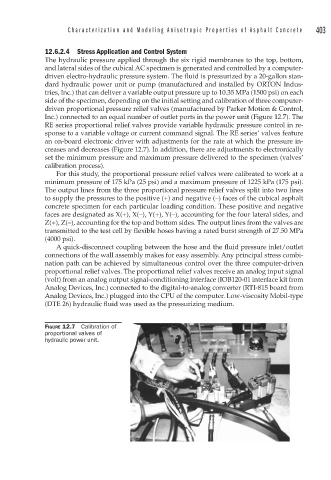
FIGURE 12.7 Calibration of
proportional valves of
hydraulic power unit.