
Page 18 - Mechanics of Microelectromechanical Systems
P. 18
1. Stiffness basics 5
where the compliance matrix links the deformations to the loads. Equations
(1.8) and (1.9) indicate that the end deflection can be produced by linearly
superimposing (adding) the separate effects of and As shown later on,
Equations (1.5) and (1.6), as well as Eqs. (1.8) and (1.9) indicate that three
different stiffnesses or compliances, namely: two direct (linear and rotary)
and one crossed, define the elastic response at the free end of a cantilever.
More details on the spring characterization of fixed-free microcantilevers that
are subject to forces and moments producing bending will be provided in this
chapter, as well as in Chapter 2, by defining the associated stiffnesses or
compliances for various geometric configurations
Example 1.1
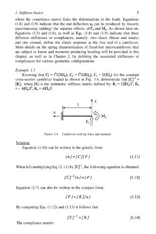
Knowing that for the constant
cross-section cantilever loaded as shown in Fig. 1.4, demonstrate that
where [K] is the symmetric stiffness matrix defined by:
Figure 1.4 Cantilever with tip force and moment
Solution:
Equation (1.10) can be written in the generic form:
When left-multiplying Eq. (1.11) by the following equation is obtained:
Equation (1.7) can also be written in the compact form:
By comparing Eqs. (1.12) and (1.13) it follows that:
The compliance matrix: