
Page 20 - Mechanics of Microelectromechanical Systems
P. 20
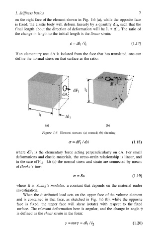
1. Stiffness basics                                                 7
         on the right face of the element shown in Fig.  1.6 (a), while the opposite face
         is fixed, the elastic body will deform linearly by a quantity   such that the
         final  length about the direction of deformation will be   The  ratio  of
         the change in length to the initial length is the linear strain:


         If an elementary area dA is isolated from the face that has translated, one can
         define the normal stress on that surface as the ratio:


                        Figure 1.6 Element stresses: (a) normal; (b) shearing


          where     is the elementary  force acting perpendicularly on  dA.  For small
          deformations and elastic materials, the stress-strain relationship is linear, and
          in the case of Fig. 1.6 (a) the normal stress and strain are connected by means
          of Hooke’s  law:


          where E is Young’s  modulus, a constant that depends on the material  under
          investigation.
              When the distributed  load acts on the upper face of the volume element
          and  is contained  in that face,  as sketched in Fig. 1.6 (b), while the opposite
          face is  fixed, the  upper  face  will  shear (rotate)  with  respect to  the  fixed
          surface. The relevant deformation here is angular, and the change in  angle
          is defined as the shear strain in the form: