
Page 19 - Mechanics of Microelectromechanical Systems
P. 19
6 Chapter 1
is now inverted and the resulting stiffness matrix is:
An explanation of the minus sign in front of the cross-stiffness in Eq. (1.16)
will be provided in Example 1.15 of this chapter.
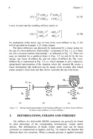
The direct stiffnesses can physically be represented by a linear spring (in
the case of a force-deflection relationship) – as pictured in Fig 1.1, or a rotary
one (for a moment-rotation relationship) – as indicated in Fig. 1.2. These two
cases are sketched for a cantilever beam in Figs. 1.5 (a) and (b) by the two
springs, one linear of stiffness and one rotary of stiffness The cross-
stiffness is represented in Fig. 1.5 (c), which attempts to give a physical,
spring-based representation of the situation where the moment creates a
linear deformation (the deflection by means of the eccentric disk which
rotates around a fixed shaft and thus moves vertically the tip of the beam.
Figure 1.5 Spring-based representation of the bending stiffnesses: (a) direct linear stiffness;
(b) direct rotary stiffness; (c) cross-stiffness
3. DEFORMATIONS, STRAINS AND STRESSES
The stiffness of a deformable MEMS component can generally be found
by prior knowledge of the corresponding deformations, strains and/or
stresses. The deformations of elastic bodies under load can be linear
(extension or compression) or angular, and Fig. 1.6 contains the sketches that
illustrate these two situations. When a constant pressure is applied normally