
Page 33 - Mechanics of Microelectromechanical Systems
P. 33
20 Chapter 1
and the minus sign indicates that produces compression of the segment
limited by the point of abscissa x and the end 1. There is obviously no torsion
acting on the microcantilever, but the shear force is:
where the plus sign shows compliance with the rule mentioned above,
because this component tends to rotate the considered segment in a clockwise
direction when this segment is allowed to rotate about point P. Similarly, the
bending moment at point x is:
and it is positive because tends to sagg the portion 1-P with respect to
point P which is considered fixed.
4.6 Boundary Conditions, Determinate/Indeterminate
Systems
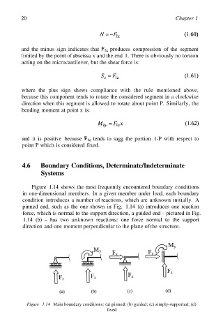
Figure 1.14 shows the most frequently encountered boundary conditions
in one-dimensional members. In a given member under load, each boundary
condition introduces a number of reactions, which are unknown initially. A
pinned end, such as the one shown in Fig. 1.14 (a) introduces one reaction
force, which is normal to the support direction, a guided end – pictured in Fig.
1.14 (b) – has two unknown reactions: one force normal to the support
direction and one moment perpendicular to the plane of the structure.
Figure 1.14 Main boundary conditions: (a) pinned; (b) guided; (c) simply-supported; (d)
fixed