
Page 81 - Mechanics of Microelectromechanical Systems
P. 81
68 Chapter 2
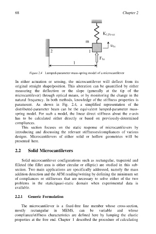
Figure 2.4 Lumped-parameter mass-spring model of a microcantilever
In either actuation or sensing, the microcantilever will deflect from its
original straight shape/position. This alteration can be quantified by either
measuring the deflection or the slope (generally at the tip of the
microcantilever) through optical means, or by monitoring the change in the
natural frequency. In both methods, knowledge of the stiffness properties is
paramount. As shown in Fig. 2.4, a simplified representation of the
distributed-parameter beam can be the equivalent lumped-parameter mass-
spring model. For such a model, the linear direct stiffness about the z-axis
has to be calculated either directly or based on previously-determined
compliances.
This section focuses on the static response of microcantilevers by
introducing and discussing the relevant stiffnesses/compliances of various
designs. Microcantilevers of either solid or hollow geometries will be
presented here.
2.2 Solid Microcantilevers
Solid microcantilever configurations such as rectangular, trapezoid and
filleted (the fillet area is either circular or elliptic) are studied in this sub-
section. Two main applications are specifically addressed, namely the mass
addition detection and the AFM reading/writing by defining the minimum set
of compliances or stiffnesses that are necessary to solve either of the two
problems in the static/quasi-static domain when experimental data is
available.
2.2.1 Generic Formulation
The microcantilever is a fixed-free line member whose cross-section,
mostly rectangular in MEMS, can be variable and whose
compliance/stiffness characteristics are defined here by lumping the elastic
properties at the free end. Chapter 1 described the procedure of calculating