
Page 59 - Mechatronic Systems Modelling and Simulation with HDLs
P. 59
48 3 MODELLING AND SIMULATION OF MIXED SYSTEMS
question are cleared from the input places, new markings are generated at the
output places and predefined actions may be performed where applicable. Such a
network can be formulated in very compact form using the tools of predicate logic,
e.g. in the Prolog language, see Negretto [295]. In this connection, a marking at a
place conveys the information that a predicate assigned to that place is fulfilled. In
order also to correctly take account of the timing of the individual components it
is necessary to add in a concept of time. So in [47] two delays are assumed for a
transition. One relates to the period of time for which the markings must be present
at the input places before the associated transition can fire. The other describes the
time that elapses between the firing of the transition and the generation of the
output markings.
Modelling of discrete relationships
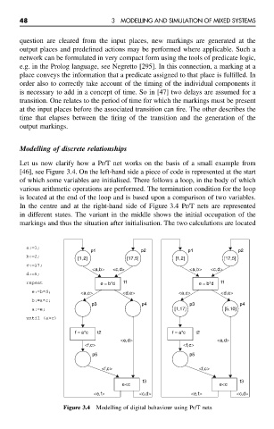
Let us now clarify how a Pr/T net works on the basis of a small example from
[46], see Figure 3.4. On the left-hand side a piece of code is represented at the start
of which some variables are initialised. There follows a loop, in the body of which
various arithmetic operations are performed. The termination condition for the loop
is located at the end of the loop and is based upon a comparison of two variables.
In the centre and at the right-hand side of Figure 3.4 Pr/T nets are represented
in different states. The variant in the middle shows the initial occupation of the
markings and thus the situation after initialisation. The two calculations are located
a:=1;
p1 p2 p1 p2
b:=2;
[1,2] [17,5] [1,2] [17,5]
c:=17;
<a,b> <c,d> <a,b> <c,d>
d:=5;
repeat e = b*d t1 e = b*d t1
e:=b*d; <a,c> <d,e> <a,c> <d,e>
b:=a*c;
p3 p4 p3 p4
a:=e; [1,17] [5,10]
until (a>c)
f = a*c t2 f = a*c t2
<e,d> <e,d>
<f,c> <f,c>
p5 p5
<f,c> <f,c>
t3 t3
e<c e<c
<e,f> <c,d> <e,f> <c,d>
Figure 3.4 Modelling of digital behaviour using Pr/T nets