
Page 64 - Mechatronic Systems Modelling and Simulation with HDLs
P. 64
3.4 DOMAIN-INDEPENDENT DESCRIPTION FORMS 53
Table 3.2 Assignment of magnitudes and elements in bond graphs
Bond graphs Electronics Mechanics, translational Mechanics, rotational
Effort Voltage Force Torque
Flow Current Velocity Angular velocity
C element Capacitor Spring stiffness Torsional spring stiffness
I element Inductor Mass inertia Moment of inertia
R element Resistor Damping, translational Damping, rotational
Transmission element Transformer Lever, pulley block Gears
I
F 4
2
m 1 a:b m 2
SF 4 p 5 TF 6 p
(a:b)
1
k 3 3
I C
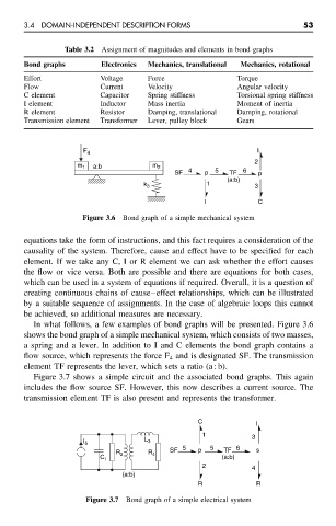
Figure 3.6 Bond graph of a simple mechanical system
equations take the form of instructions, and this fact requires a consideration of the
causality of the system. Therefore, cause and effect have to be specified for each
element. If we take any C, I or R element we can ask whether the effort causes
the flow or vice versa. Both are possible and there are equations for both cases,
which can be used in a system of equations if required. Overall, it is a question of
creating continuous chains of cause–effect relationships, which can be illustrated
by a suitable sequence of assignments. In the case of algebraic loops this cannot
be achieved, so additional measures are necessary.
In what follows, a few examples of bond graphs will be presented. Figure 3.6
shows the bond graph of a simple mechanical system, which consists of two masses,
a spring and a lever. In addition to I and C elements the bond graph contains a
flow source, which represents the force F 4 and is designated SF. The transmission
element TF represents the lever, which sets a ratio (a : b).
Figure 3.7 shows a simple circuit and the associated bond graphs. This again
includes the flow source SF. However, this now describes a current source. The
transmission element TF is also present and represents the transformer.
C I
1 3
L 3
I 5
SF 5 p 5 TF 6 s
R 2 R 4
C 1 (a:b)
2
4
(a:b)
R R
Figure 3.7 Bond graph of a simple electrical system