
Page 67 - Mechatronic Systems Modelling and Simulation with HDLs
P. 67
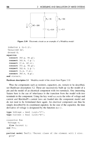
56                          3  MODELLING AND SIMULATION OF MIXED SYSTEMS


                                                   R 1  = 10   R 2  = 100


                                    ~  AC = 220
                                                    C 1  = 0.01  L 1  = 0.1


                         Figure 3.10  Electronic circuit as an example of a Modelica model

                Inductor L (L=0.1);
                VsourceAC AC;
                Ground G;
               equation
                 connect (AC.p, R1.p);
                 connect (R1.n, C.p );
                 connect (C.n, AC.n);
                 connect (R1.p, R2.p);
                 connect (R2.n, L.p );
                 connect (L.n, C.n);
                 connect (AC.n, G.p);
               end circuit;

               Hardware description 3.1 Modelica model of the circuit from Figure 3.10
                 Thus the components such as resistors, capacitors, etc. remain to be described,
               see Hardware description 3.2. These are successively built up via the model of a
               pin and the model of an electrical component with two terminals. One interesting
               feature here is the use of inheritance in the transition from the model with two
               terminals to the component. Using the key word extends the roles of voltage and
               current and Kirchhoff’s current laws are loaded into the component model and
               do not need to be formulated there again. An electrical component can thus be
               simply described by its constituent equation. In the case of the capacitor, the time
               derivative of voltage is designated by the function der().

               type Voltage = Real (unit="V");
               type Current = Real (unit="A");
               ...
               connector Pin
                Voltage v;
                 flow Current i;
               end Pin;
               ...
               partial model TwoPin "Parent class of the element with 2 elec.
                 pins"