
Page 70 - Mechatronic Systems Modelling and Simulation with HDLs
P. 70
3.5 SIMULATOR COUPLING 59
Synchroni- Simulator
sation
Solver
interface
User
User
interface
Display of
outputs
Design
data
Display
tool
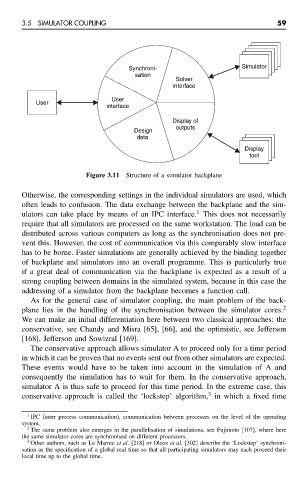
Figure 3.11 Structure of a simulator backplane
Otherwise, the corresponding settings in the individual simulators are used, which
often leads to confusion. The data exchange between the backplane and the sim-
1
ulators can take place by means of an IPC interface. This does not necessarily
require that all simulators are processed on the same workstation. The load can be
distributed across various computers as long as the synchronisation does not pre-
vent this. However, the cost of communication via this comparably slow interface
has to be borne. Faster simulations are generally achieved by the binding together
of backplane and simulators into an overall programme. This is particularly true
if a great deal of communication via the backplane is expected as a result of a
strong coupling between domains in the simulated system, because in this case the
addressing of a simulator from the backplane becomes a function call.
As for the general case of simulator coupling, the main problem of the back-
plane lies in the handling of the synchronisation between the simulator cores. 2
We can make an initial differentiation here between two classical approaches: the
conservative, see Chandy and Misra [65], [66], and the optimistic, see Jefferson
[168], Jefferson and Sowizral [169].
The conservative approach allows simulator A to proceed only for a time period
in which it can be proven that no events sent out from other simulators are expected.
These events would have to be taken into account in the simulation of A and
consequently the simulation has to wait for them. In the conservative approach,
simulator A is thus safe to proceed for this time period. In the extreme case, this
3
conservative approach is called the ‘lockstep’ algorithm, in which a fixed time
1
IPC (inter process communication), communication between processes on the level of the operating
system.
2 The same problem also emerges in the parallelisation of simulations, see Fujimoto [107], where here
the same simulator cores are synchronised on different processors.
3 Other authors, such as Le Marrec et al. [218] or Olcoz et al. [302] describe the ‘Lockstep’ synchroni-
sation as the specification of a global real time so that all participating simulators may each proceed their
local time up to the global time.