
Page 116 - Mechatronics for Safety, Security and Dependability in a New Era
P. 116
Ch21-I044963.fm Page 100 Tuesday, August 1, 2006 3:30 PM
Ch21-I044963.fm
100
100 Page 100 Tuesday, August 1, 2006 3:30 PM
DOF along the hole axis must be specified. Until the work piece (end effector) is pulled away thorough
the second hole (see Fig. 4(d)), J1-J5 exist before the first wall. Therefore, five joints ofJ^-Jw exist
before the second wall before Jn is pulled away through this hole. After/n is pulled away through this
hole, six joints of J(,-J\\ exist before the wall. Therefore, it is necessaiy to select five joints among the
six to pull away link I12. As the configuration on which the combination of joint angles for realizing
the passage through the hole can be changed and must be selected, ten middle configurations are set on
the way from a given initial configuration (see Fig. 4 (1) ) to the final configuration (see Fig. 4 (a)).
They are concretely as follows:
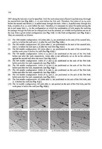
(1) The 10th middle configuration: All joints after J10 are positioned on the axis of the second hole,
and J10 is before the wall and J\ 1 is after the wall (See Fig. 4 (b) ).
(2) The 9th middle configuration: All joints after J\\ are positioned on the axis of the second hole,
and Jn is before the wall and Jn is after the wall (See Fig. 4 (c)).
(3) The 8th middle configuration: All joints after J\ 1 are positioned on the axis of the second hole,
and the work piece is before the wall (See Fig. 4 (d) ).
(4) The 7th middle configuration: Joints of Je and J 1 are positioned on the axis of the first hole
before and after the wall, respectively. Joints after J s are arbitrarily set as far as the collision
against the second wall does not occur (See Fig. 4 (e)).
(5) The 6th middle configuration: Joints of J7 and Jn are positioned on the axis of the first hole
before and after the wall, respectively (see Fig. 4 (f)).
(6) The 5th middle configuration: Joints of Jg and Jg are positioned on the axis of the first hole
before and after the wall, respectively (see Fig. 4 (g)).
(7) The 4th middle configuration: Joints of J 9 and J lo are positioned on the axis of the first hole
before and after the wall, respectively (see Fig. 4 (h) ).
(8) The 3rd middle configuration: Joints of J\Q and Ju are positioned on the axis of the first hole
before and after the wall, respectively (see Fig. 4 (i)).
(9) The 2nd middle configuration: All joints after Jn are positioned on the axis of the first hole, and
Jn is before the wall (see Fig. 4 (j)).
(10) The 1st middle configuration: All joint after J\\ are posited on the axis of the first hole, and the
work piece is before the wall (see Fig. 4 (k)).
(e) 7th middle configuration (f) 6th middle configuration (g) 5th middle configuration (h) 4th middle configuration