
Page 117 - Mechatronics for Safety, Security and Dependability in a New Era
P. 117
Ch21-I044963.fm Page 101 Tuesday, August 1, 2006 3:30 PM
Page 101
1, 2006
Tuesday, August
Ch21-I044963.fm
3:30 PM
101
101
(i) 3rd middle configuration (j) 2nd middle configuration (k) 1st middle configuration (1) Initial pose
Figure 4: A result of simulation (14 DOF robot passes through two cylindrical holes in two thick walls)
Combination of Joint Angles used for Passage thorough Hole
For example, how to decide the combination of joint angles for realizing the passage through the hole
from the 9th middle configuration to the 8th one is explained here. Tn this transition of configuration,
Jw is positioned before the wall on the axis of the second hole, and the work piece is pulled out
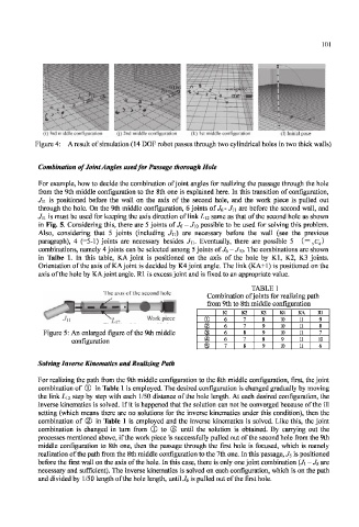
through the hole. On the 9th middle configuration, 6 joints of J 6 - J n are before the second wall, and
J n is must be used for keeping the axis direction of link L 12 same as that of the second hole as shown
in Fig. 5. Considering this, there are 5 joints of J 6 - Jw possible to be used for solving this problem.
Also, considering that 5 joints (including Jn) are necessary before the wall (see the previous
paragraph), 4 (=5-1) joints are necessary besides J\\. Eventually, there are possible 5 (= 5 C 4 )
combinations, namely 4 joints can be selected among 5 joints of Je - Jio. The combinations are shown
in Talbe 1. In this table, KA joint is positioned on the axis of the hole by Kl, K2, K3 joints.
Orientation of the axis of KA joint is decided by K4 joint angle. The link (KA+1) is positioned on the
axis of the hole by KA joint angle. Rl is excess joint and is fixed to an appropriate value.
TABLE 1
The axis of the second hole
Combination of joints for realizing path
from 9th to 8th middle configuration
Kl K2 K3 K4 KA Rl
Work piece (I) 6 7 8 10 11 9
® 6 7 9 10 11 8
Figure 5: An enlarged figure of the 9th middle 6 8 9 10 11 7
configuration © 6 7 8 9 II 10
© 7 8 9 10 11 6
Solving Inverse Kinematics and Realizing Path
For realizing the path from the 9th middle configuration to the 8th middle configuration, first, the joint
combination of CD in Table 1 is employed. The desired configuration is changed gradually by moving
the link L\i step by step with each 1/50 distance of the hole length. At each desired configuration, the
inverse kinematics is solved. If it is happened that the solution can not be converged because of the ill
setting (which means there are no solutions for the inverse kinematics under this condition), then the
combination of (2) in Table 1 is employed and the inverse kinematics is solved. Like this, the joint
combination is changed in turn from ® to © until the solution is obtained. By carrying out the
processes mentioned above, if the work piece is successfully pulled out of the second hole from the 9th
middle configuration to 8th one, then the passage through the first hole is focused, which is namely
realization of the path from the 8th middle configuration to the 7th one. In this passage, J s is positioned
before the first wall on the axis of the hole. In this case, there is only one joint combination (J\ -J 5 are
necessary and sufficient). The inverse kinematics is solved on each configuration, which is on the path
and divided by 1/50 length of the hole length, until^ is pulled out of the first hole.