
Page 121 - Mechatronics for Safety, Security and Dependability in a New Era
P. 121
Ch22-I044963.fm Page 105 Tuesday, August 1, 2006 3:32 PM
Tuesday, August
3:32 PM
1, 2006
Ch22-I044963.fm
Page 105
105
105
Step 2.2; According to the behavior definition, the system decides the system behavior that
includes action for designer and maintenance of the design information etc
4. UPSTREAM DESIGN STAGE REQUIREMENTS FOR PRINCIPAL ARCHITECTURE
During the upstream design stage, the main purpose is to achieve the functional requirements. Shapes,
positions, etc. are very simple or vague. However, this information is very important to achieve the
main requirements and should be observed in the subsequent design stages. Therefore, to support the
design process flow it is important to handle simple or vague information and to transmit this
information to the downstream process. Moreover, the case that a simple geometric element expresses
some function, that will become a more detailed model or a space function. Thus, handling this space
is one of the important items to support during the design process.
Geometrical simplicity consideration
At the upstream design stage, geometric elements express a sub-assembly or part, even if the
geometric element is very simple like a line or plane. For example, when a line shows an axis in the
upstream design stage, it is necessary to be able to set the design information to a line, surface
roughness, material type, weight limitation, etc.. Thus, the mechanism should have the capability to set
the design information to targets regardless of geometrical type, where geometrical type means edge,
face or solid. The principal architecture fulfills this functionality.
However, it is important to consider is the case of geometric type change; that is not only the case of
change of the element itself, but also the case of geometric type change, it is necessary to transmit the
design information and intention to the final shape from the simple initial shape. This is a requirement
for the framework, transmitting the design information defined in an initial element to a newly
generated element.
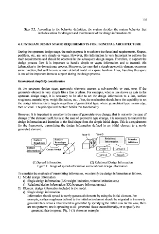
face-A face-B
Relational
Surface Surface Behavior
Roughness Roundness Information definition
Spread
Create Model Group-1 Group-2
information
face-A face-B
(1) Spread Information (2) Relational Design Information
Figure 1: Image of spread information and relational design information
To consider the methods of transmitting information, we classify the design information as follows.
1) Model design information
a) Single design information (EX: weight limitation, volume limitation etc.)
b) Relational design information (EX: boundary information etc.)
2) Element design information included in the model
a) Single design information
Information should spread to newly generated elements by using the initial element. For
example, surface roughness defined to the initial axis element should be migrated to the newly
generated face when a rotated solid is generated by specifying the initial axis. In this case, there
are two patterns; one is spreading to all generated faces unconditionally, or to specify the
generated face to spread. Fig. 1-(1) shows an example.