
Page 166 - Mechatronics for Safety, Security and Dependability in a New Era
P. 166
Ch31-I044963.fm Page 150 Tuesday, August 1, 2006 3:06 PM
Ch31-I044963.fm
150
150 Page 150 Tuesday, August 1, 2006 3:06 PM
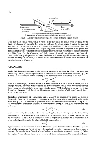
Acceleration
Fixed anchor
n'- number of beam \ AZ
p : density displacement/
t=h in this research on account of fabrication process.
Displacement of mass plate is detected when acceleration is applied
Figurel: Accelerometer comprising a proof mass plate and support beams
holds true under tensile stress, while kcc]/l J holds true under no tensile stress according to the
theory of strength of materials. Lowering the stiffness k, which means lowering the resonant
frequency f r, is important in order to increase the sensitivity of the accelerometer, since the
sensitivity is \/(2Kf rf. Therefore, spiral shaped long beam structure is proposed in this paper. And
free standing Parylene suspended structures are practically fabricated. Vibrations of them are observed
by a LDV (Laser Doppler Vibrometer) and their resonant frequencies are obtained experimentally.
These results have good agreement with simulated ones. This means large / is necessary for lowering
resonant frequency. As the result, it is proved that the structure with spiral shaped beam is effective for
lowering the resonant frequency.
FEM ANALYSIS
Mechanical characteristics under tensile stress are numerically simulated by using FEM. FEMLAB
produced by Comsol, Inc. is adopted as FEM software. In the case of the structure shown in Fig.l, the
stiffness k is analytically calculated according to the theory of strength of materials as follows:
3
, nEbh
where / is beam length, b is beam width, h is beam thickness, n is the number of beams, and E is
Young's modulus. However, these equations are derived under no tensile stress. In order to estimate
these mechanical characteristics under severe tensile stress, FEM simulation is carried out. Tn this
simulation, it is assumed t=h since it is difficult to fabricate the structure of which t and h are different,
where t is plate thickness.
Dependence of deflection AZ on the beam size of /, b, h{=t) are simulated. The results are shown in
Figs.2-4. In Fig.2, AZ is increased in proportion to the first power of the beam length under tensile
stress. In Fig.3, AZ is decreased in proportion to the first power of the beam width b. In Fig.4, AZ
has no dependence on the beam thickness h. From the results of Figs.2-4 totally, the relation holds true
as follows:
^ =PWLfgJ_
hz =
k k b '
where p is density, W is plate width, L is plate length and a is the input acceleration. Taking
account that AZ is proportional to tlk as shown in the former part in Eq.(2), and taking account that
the condition of t=h holds true, it is concluded that k is proportion to h, since AZ is irrespective of h
as shown in Fig.4. Eventually, the relationship holds true as follows:
kccbj (3)
Eq.(3) under tensile stress is derived from FEM simulation, and it is different from that of Eq.(l) under
no intrinsic stress derived from the theory of strength of materials. It means a rather longer beam is
necessary for lowering the stiffness k, which also leads to lowering the resonant frequency /,. When
the length of beam is longer, larger space is required. Considering space efficiency, spiral shaped