
Page 163 - Mechatronics for Safety, Security and Dependability in a New Era
P. 163
Ch30-I044963.fm Page 147 Thursday, July 27, 2006 7:17 AM
Page 147
Thursday, July 27, 2006
7:17 AM
Ch30-I044963.fm
147
147
- = C'A, (5)
1 * 1 CO dt
As mentioned above, six components of acceleration and angular acceleration can be calculated from
measured accelerations along the direction of each link by using constant coefficient matrix C in
advance.
CALCULATING OPTIMUM STRUCTURAL PARAMETER
The coefficient matrix C should be nonsingular matrix, and the calculation results tend to come under
the influence of misalignment and measurement errors of each sensors when the matrix C is near
singular point. Since we use that platform as not an actuator but a base structure of measuring
instrument, we found the optimal structure based on Stewart Platform to reduce the influence of
misalignment. Two plates are in a direction parallel each other. The centerline, which connects
centers of plate, is vertical to both plates. And nodes are placed evenly spaced apart (120degrees
interval). In this time, we calculated normalized radius of upper plate 'R' and normalized distance
between two plates 'H' according the centerline, when bottom plate radius is fixed to 1. By adding
virtual error to the accelerations of (a, to) up to 10%, the set of calculated accelerations (tic, a>c) from
equation 5 and the average of evaluation value S calculated from equation 6 were obtained. The
optimal radius of upper plate R and the optimum distance between both plates H were found out by
making average value of S minimum.
-a
(6)
a
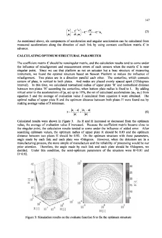
Calculated results were shown in Figure 3. As R and H increased or decreased from the optimum
value, the average of evaluation value S increased. Because the coefficient matrix became close to
the singular point, the calculation results tended to come under the influence of added error. After
searching optimum values, the optimum radius of upper plate R should be 0.83 and the optimum
distance between two plates H should be 0.93. On the optimum structure with these parameters,
angle made by each link and each plate was 43degrees. However, when the detectors are in a
manufacturing process, the more simple of manufacture and the reliability of processing would be our
prior attention. Therefore, the angle made by each link and each plate should be 45degrees, we
decided. Under this condition, the semi-optimum parameters of the structure were R=0.81 and
H=0.92.
10
10
10 10
R[-] 10 10 H[-]
H[-]
Figure 3: Simulation results on the evaluate function S to fix the optimum structure