
Page 159 - Mechatronics for Safety, Security and Dependability in a New Era
P. 159
Ch29-I044963.fm Page 143 Tuesday, August 1, 2006 3:05 PM
Tuesday, August
1, 2006
3:05 PM
Page 143
Ch29-I044963.fm
143
143
V x = V(a)-V(c) (1)
V Y = V(b)-V(d) (2)
V z = V(a)+V(b)+V(c)+V(d) (3)
look a
Piezoresisor
Piezoresisor
VouL
-10*(Va+Vh+Vc+Vd>
Piezoresisor
Piezoresisor
jlOOkfi
Y direction
Figure 7: Evaluation circuit using operational amplifiers
CHARACTERISTICS OF SENSOR
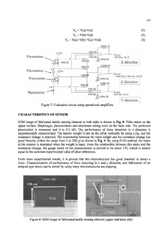
SEM image of fabricated tactile sensing element in both sides is shown in Fig. 8. Pillar exists on the
upper surface. Diaphragm, piezoresistors and aluminum wiring exist on the back side. The produced
piezoresitor is measured and it is 0.5 kfl. The performance of force detection in z direction is
experimentally characterized. The known weight is put on the pillar vertically by using a jig, and the
resistance change is detected. The relationship between the input weight and the resistance change has
good linearity within the range from 0 to 200 gf as shown in Fig. 9. By using FEM method, the strain
at the resistor is simulated when the weight is input. From the relationship between this strain and the
resistance change, the gauge factor of the pizezoresistor is proved to be about 133, which is almost
equal to the common experimental value of other references.
From these experimental results, it is proved that this microstructure has good potential to detect a
force. Characterization of performance of force detecting in x and y direction, and fabrication of an
arrayed type micro tactile sensor by using many microstructures are ongoing.
Figure 8: SEM image of fabricated tactile sensing element (upper and back side)