
Page 162 - Mechatronics for Safety, Security and Dependability in a New Era
P. 162
Ch30-I044963.fm Page 146 Thursday, July 27, 2006 7:17 AM
Ch30-I044963.fm
146
146 Page 146 Thursday, July 27, 2006 7:17 AM
there were no movable links, and this structure resulted the ease of calculation of six components from
six measured values. We described the constructing method and the calculating solution on each link
parameters. In order to confirm the validity of this method of measurement, the acceleration and
angular acceleration sensor system was manufactured.
MEASUREMENT ALGORITHM
The calculating solution was worked out by thinking that the upper plate was moving as six links were
expanding and/or contracting, and that the motion of links were measured by single axis accelerometer.
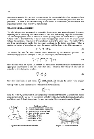
The calculating algorithm could be resolved as follows by using points and vectors shown in Figure 1.
When a vector is described in one of the two plate, the superscripts written on the left of each vector
indicate the coordinate. Superscript 'b' means bottom plate and 'p' upper plate. The matrix ' R p' is
coordinate transformation matrix from the upper coordinate to the bottom coordinate. When a
position and posture of upper plate was given, the vector / ; could be shown by the following equation.
b b b
li = tt-%+ R/pi (1)
p
The vectors ' pi and ib bi were constant vector determined by the structural specimen, By
differentiating equation with respect to time, the following equation can be obtained.
d% da \Rot(k r,dfi)-E (2)
dt dt + \ dt 'K/P,
Since all links would not expand and contract, the infinitesimal deformation caused by the motion of
upper plate would return to zero in a very short time. Therefore, the velocity of links can be
expanded by introducing next equation.
(3)
dt dT
Since the components of each terms '_ Rot(k T,d$)- E da include the vector v and angular
dt dt ' dt
velocity vector w, next equation can be obtained from above equations.
= c~V, (4)
Here, the vector V L is composed of link's expanding velocities and the matrix C is coefficient matrix
about components of v and it>. In our proposal, all links would not expand and contract, therefore the
coefficient matrix C should be constant. In same manner, the following equation can be obtained.
Points and vectors
Origin of coordinates in bottom plate
Origin of coordinates in upper plate
Node of i-th link to bottom plate
Node of i-th link to upper plate
Vector from B o to B
Vector from P o to P ,
» i : Vector from B o to P o
11: Vector from B -, to P -,
Figure 1: Model of Stewart Platform Figure 2: Acceleration vector