
Page 170 - Mechatronics for Safety, Security and Dependability in a New Era
P. 170
Ch32-I044963.fm Page 154 Monday, August 7, 2006 11:28 AM
Ch32-I044963.fm
154
154 Page 154 Monday, August 7,2006 11:28 AM
So, in order to solve these problems and realize an efficient estimation, we propose a new prediction
procedure. In the proposed procedure, the cutting depth on cutting edge in machining is calculated by
a new "sequence-free" algorithm, which is based on the idea of tool swept volume (Wang W.P. 1986).
Because the new algorithm does not require the explicit information of workpiece shape, it is thought
that immediate and accurate prediction of cutting error is attained regardless of both the complexity
of workpiece shape and sequence of tool moving in NC program.
NEW PREDICIOTN PROCEDURE OF CUTTING ERROR DISTRIBUTION
As mentioned above, difiicultness of the prediction is caused by repetition of workpiece shape
estimation process. So, in the new proposed procedure, the cutting depth is directly estimated using
NC program and workpiece initial shape. This process can be performed regardless sequence of
change of workpiece shape in machining, as shown in Figure 1.
Fr Chuck distort ion
Chuck distortion
NC Program
G00X..Y..Z...F...
G01X..Y...F...
G01X..Y... Ft Cutting i l i
Cutting
Tool
Cutting depth Ft force r c e u t Tool
f o
deflection
Estimation of finished workpiece shape Cutting depth Fr r\—ut edeflection
H
Cutting error r
Tool Position (x,y,z) | )Cutting ro
Tool moving step i th
Tool rotation angle j deg Estimation of cutting depth Estimation of Estimation of cutting edge
p timation of rnfl ing edge
for each part of cutting edge
instantaneous cutting force displacement as c
displacement as cutting error
Arrangement of estimation point
Specification of tool rotation angle and position
Figure 1: Proposed procedure for prediction of cutting error distribution
The proposed procedure consists of the following four estimation steps.
1. Arrangement of estimation point on nominal surface of finished workpiece. Nominal surface is
workpiece shape estimated under assumption that the tool deflection did not happen.
2. Specification of tool rotation angle and position at the moment each point was generated.
3. Estimation of cutting depth on each part of cutting edge and prediction of total cutting force.
4. Prediction of displacement on the part of cutting edge.
These steps are repeated for each estimation point on the nominal surface of finished workpiece. In
the following sections, we explain the details from 1st to 3rd step in case of 3-axis controlled
machining with ball end mill.
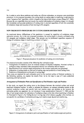
Arrangement of Estimation Point and Specification of Tool Rotation Angle and Position
In this study, we regard the cutting error as the distance between the nominal surface and actual
machined workpiece surface. In order to estimate the distance, we arrange estimation points on the
nominal workpiece surface and specify both tool rotation angle and position at the moment the
estimation points was appeared. So, we introduce Z-map representation (Takeuchi Y. 1989) and the
idea of tool swept volume for estimation of workpiece shape at the time when machining is finished.
As illustrated in Figure 2, By finding the tool moving step which distance \Pij-pOij\ is the smallest, we
can specify the coordinate of estimation point p;/, tool rotation angle <% and tool position fc,y.
tc vn
Tool swept volume TSV ij ij i Tool radius r
Tool swept volume TSV n
n
Tool feed direction
Tool feed direction
e(q) θ ij
Z p tse u
Y ij n v
X tss n q y e(q)
tc =stss +(1-s)tse j
ij n n x
|p -tc |=r (0 s 1) i p0 ij
ij ij
Figure 2: Arrangement of estimation point and specification of tool rotation angle and position