
Page 174 - Mechatronics for Safety, Security and Dependability in a New Era
P. 174
Ch33-I044963.fm Page 158 Tuesday, August 1, 2006 3:12 PM
Ch33-I044963.fm
158
158 Page 158 Tuesday, August 1, 2006 3:12 PM
the productivity of injection molding is improved ifthe time forthe cycle can be shortened. More than a half of the
cycle time is wasted in the stage to solidify the inj ectedmaterial. Consequently, the shortening of the solidifying time
results in improvement of molding productivity. The solidification is generally accomplished by cooling a mold by
means of coolant flow which runs through water channels built in mold. Water channels are pipelines fabricated
in a mold. They are usually made by drilling. Namely, they consist of a straight hole or a series of straight holes.
As a result, the shape of a water channel is polygonal line. This causes the restriction of the degree of freedom in
their position and shape.
To achieve the optimal position and shape of water channels, it is demanded to develop a curved hole machining
method, Goto et al. (2002), Ichiyasu et al. (1997), Uchiyama & Shibasaki (2004). This leads to the reduction of
the cycle time in molding since the solidifying time can be shortened by the optimal water channels. Asa result, it
will be possible to improve productivity of injection molding. To meet the requirement, the authors have also
developed the devices which can machine curved holes, Ishida & Takeuchi (2002), (2004). The devices can
control the moving trajectory of a tool electrode attached to an electrical discharge machine (EDM) and simulta-
neously make the electrode perform electrical discharge machining. Ifthe electrode moving trajectory is curved
one, the curved hole can be machined, which has the identical shape with the envelope of electrode moving locus.
Additionally, the device is able to fabricate various-shaped curved holes since the electrode moving trajectory
can be controlled by a software.
However, the device has a problem that the diameter of the machined curved holes is too large to employ them
as water channels. To solve the problem, in the study, the diameter of the former electrode, 20mm, is reduced to
a half of it. According to the size reduction of the electrode, the parts constituting the electrode and the peripheral
parts around the electrode are redesigned. Concretely, some parts are omitted, the size of some other parts is
reduced, or assembling method is changed. From the results in the motion and machining experiments, it is found
that the redesigned device is effective and can machine the curved holes of half size diameter.
CURVED HOLE MACHINING DEVICE
Structure and Motion of the Device
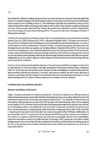
Figure 1 illusfrates a schematic view of the developed device. The device is installed on an EDM and consists of
a helical compression spring, an electrode for electrical discharge machining, wires, pulleys, three ball screws with
servomotors, motor drivers, a linear scale, and a personal computer (PC). The electrode is mounted on the end
of the spring, which is connected to a head of the EDM through a shaft and a tabular jig. Three wires are fastened
in equal angles of 120° on the end of the electrode side of the spring and are respectively led to the nuts of the ball
screws through the pulleys on the tabular jig. Each servomotor is connected with the PC through the motor
driver. On the other hand, a L-shaped jig rests on the bottom of a working tank of the EDM. On the wall of the
L-shaped jig, the linear scale is mounted so that it can measure the position of the EDM head. Additionally, it is
also connected to the PC. In summary, the PC can measure the EDM head position and can control respective
servomotors, i.e., respective feeds of the wires at the same time. Consequently, this device can independently
control the wire feeds according to the EDM head feed. In the study, the PC controls the wire feeds so that the
feeding amounts of two wires on the left side are identical and that they are different from the feeding amount of
the wire on the right side and so that the relationship between the EDM head feed and the wire feeds can be
expressed as follows:
Ls\=N\h,Lsl = Nlh (1)