
Page 176 - Mechatronics for Safety, Security and Dependability in a New Era
P. 176
Ch33-I044963.fm Page 160 Tuesday, August 1, 2006 3:12 PM
Ch33-I044963.fm
160
160 Page 160 Tuesday, August 1, 2006 3:12 PM
Spring Spring
Electrode
Electrode
10mm
10mm 10mm
Electrode
Electrode
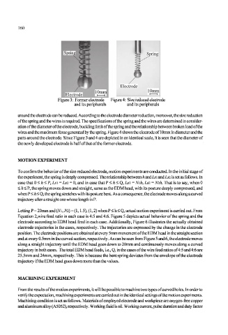
Figure 3: Former electrode Figure 4: Size reduced electrode
and its peripherals and its peripherals
around the electrode can be reduced. According to the electrode diameter reduction, moreover, the size reduction
of the spring and the wires is required. The specifications of the spring and the wires are determined in consider-
ation of the diameter of the electrode, buckling limit of the spring and the relationship between broken load of the
wires and the maximum force generated by the spring. Figure 4 shows the electrode of 10mm in diameter and the
parts around the electrode. Since Figure 3 and 4 are depicted in an identical scale, it is seen that the diameter of
the newly developed electrode is half of that of the former electrode.
MOTION EXPERIMENT
To confirm the behavior of the size reduced electrode, motion experiments are conducted. In the initial stage of
the experiment, the spring is deeply compressed. The relationship between h and Ls\ and Lsi is set as follows. In
case that 0 < h < P, Lsi = Lsi = 0, and in case that P < h < Q, Lsi = Nih, Lsi = Nih. That is to say, when 0
< h < P, the spring moves down and straight, same as the EDM head, with its posture deeply compressed, and
when P < h < Q, the spring stretches with its posture bent. As a consequence, the electrode moves along a curved
trajectory after a straight one whose length is P.
Letting P = 20mm and (M, Nl) = (1,1.5), (1,2) when P < h < Q, actual motion experiment is carried out. From
Equation 2,wire feed ratio in each case is 4:5 and 4:6. Figure 5 depicts actual behavior of the spring and the
electrode according to EDM head feed in each case. Additionally, Figure 6 illustrates the actually obtained
electrode trajectories in the cases, respectively. The trajectories are expressed by the change in the electrode
position. The electrode positions are obtained at every 5mm movement of the EDM head in the straight section
and at every 0.5mm in the curved section, respectively. As can be seen from Figure 5 and 6, the electrode moves
along a straight trajectory until the EDM head goes down to 20mm and continuously moves along a curved
trajectory in both cases. The total EDM head feeds, i.e., Q, in the cases of the wire feed ratios of 4:5 and 4:6 are
25.5mm and 24mm, respectively. This is because the bent spring deviates from the envelope of the electrode
trajectory if the EDM head goes down more than the values.
MACHINING EXPERIMENT
From the results of the motion experiments, it will be possible to machine two types of curved holes. In order to
verify the expectation, machining experiments are carried out in the identical settings of the motion experiments.
Machining condition is set as follows. Materials of employed electrode and workpiece are oxygen-free copper
and aluminum alloy (A5052), respectively. Working fluid is oil. Working current, pulse duration and duty factor