
Page 181 - Mechatronics for Safety, Security and Dependability in a New Era
P. 181
Ch34-I044963.fm Page 165 Thursday, July 27, 2006 7:23 AM
Page 165
7:23 AM
Ch34-I044963.fm
Thursday, July 27, 2006
165
165
non-rotational tool. The former is attached to a high speed air turbine spindle mounted on C table. The
latter is directly fixed on C table through a jig. A workpiece is mounted on B table in both cases.
CREATION OF V-SHAPED MICROCHANNEL ARRAY CHIP
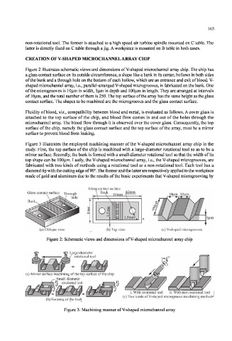
Figure 2 illustrates schematic views and dimensions of V-shaped microchannel array chip. The chip has
a glass contact surface on its outside circumference, a shape like a bank in its center, hollows in both sides
of the bank and a through hole on the bottom of each hollow, which are an entrance and exit of blood. V-
shaped microchannel array, i.e., parallel-arranged V-shaped microgrooves, is fabricated on the bank. One
of the microgrooves is lOum in width, 5|j.m in depth and lOOum in length. They are arranged at intervals
of 10|im, and the total number of them is 250. The top surface of the array has the same height as the glass
contact surface. The shapes to be machined are the microgrooves and the glass contact surface.
Fluidity of blood, viz., compatibility between blood and metal, is evaluated as follows. A cover glass is
attached to the top surface of the chip, and blood flow comes in and out of the holes through the
microchannel array. The blood flow through it is observed over the cover glass. Consequently, the top
surface of the chip, namely the glass contact surface and the top surface of the array, must be a mirror
surface to prevent blood from leaking.
Figure 3 illustrates the employed machining manner of the V-shaped microchannel array chip in the
study. First, the top surface of the chip is machined with a large-diameter rotational tool so as to be a
mirror surface. Secondly, the bank is formed with a small-diameter rotational tool so that the width of its
top shape can be 100)im. Tastly, the V-shaped microchannel array, i.e., the V-shaped microgrooves, are
fabricated with two kinds of methods using a rotational tool or a non-rotational tool. Each tool has a
diamond tip with the cutting edge of 90°. The former and the latter are respectively applied to the workpiece
made of gold and aluminum due to the results of the basic experiments that V-shaped microgrooving by
Glass contact surface
Glass contac.t surface ough \ Bank . . (|>2mm ,1-OWP,
hole .*_\— \ 16mm
Bank. \
ol
5|im
(a) Oblique view (b) Top view (c) V-shaped microgrooves
Figure 2: Schematic views and dimensions of V-shaped microchannel array chip
Large-diameter
rotational tool
(a) Mirror surface machining of the top surface of the chip
---Small-diameter
\(\ rotational tool
i. With rotational tool ii. With non-rotational tool
(c) Two kinds of V-shaped microgroove machining methods
(b) Forming of the bank
Figure 3: Machining manner of V-shaped microchannel array