
Page 177 - Mechatronics for Safety, Security and Dependability in a New Era
P. 177
Ch33-I044963.fm Page 161 Tuesday, August 1, 2006 3:12 PM
1, 2006
3:12 PM
Page 161
Tuesday, August
Ch33-I044963.fm
161
161
(a) Wire feed ratio: 4:5
20mm) B(21mm) t22mm) J(23mm) B(24mm)
(b) Wire feed ratio: 4:6
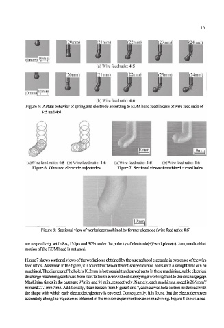
Figure 5: Actual behavior of spring and electrode according to EDM head feed in case of wire feed ratio of
4:5 and 4:6
(a)Wire feed ratio: 4:5 (b) Wire feed ratio: 4:6 (a)Wire feed ratio: 4:5 (b)Wire feed ratio: 4:6
Figure 6: Obtained electrode trajectories Figure 7: Sectional views of machined curved holes
Figure 8: Sectional view of workpiece machined by former electrode (wire feed ratio: 4:5)
are respectively set in 8A, 135(is and 30% under the polarity of electrode(+)/workpiece(-). Jump and orbital
motion of the EDM head is not used.
Figure 7 shows sectional views of the workpieces obtained by the size reduced electrode in two cases of the wire
feed ratios. As shown in the figure, it is found that two-different-shaped curved holes with a straight hole can be
machined. The diameter of the hole is 10.2mm in both straight and curvedparts. In these machining, stable electrical
discharge machining continues from start to finish even without supplying a working fluid to the discharge gap.
3
Machining times in the cases are 97min. and 91 min., respectively. Namely, each machining speed is 26.9mm /
3
min and 27.1 mm /min. Additionally, it can be seen from Figure 6 and 7, each curved hole section is identical with
the shape with which each electrode trajectory is covered. Consequently, it is found that the electrode moves
accurately along the trajectories obtained in the motion experiments even in machining. Figure 8 shows a sec-