
Page 175 - Mechatronics for Safety, Security and Dependability in a New Era
P. 175
Ch33-I044963.fm Page 159 Tuesday, August 1, 2006 3:12 PM
Tuesday, August
3:12 PM
1, 2006
Ch33-I044963.fm
Page 159
159
159
PC
Linear scale PC
Linear scale
Motor driver
EDM head
Pulleys
Ball screw
h
SL L1
Shaft
Tabular jig Servomotor Ls1 Ls2 L2
Working fluid Wires
SL
Helical
compression SL
spring
L-shaped
jig
Electrode Workpiece
Electrode
Workpiece
(b) In
(a) Initial stage
(a) Initial stage (b) In feeding
feeding
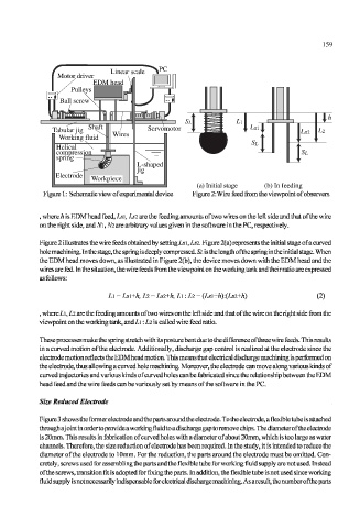
Figure 1: Schematic view of experimental device Figure 2: Wire feed from the viewpoint of observers
, where h is EDM head feed, Lsi, Lsi are the feeding amounts of two wires on the left side and that of the wire
on the right side, and M, Ni are arbitrary values given in the software in the PC, respectively.
Figure 2 illustrates the wire feeds obtained by seUingLsi,Ls2. Figure 2(a) represents the initial stage of a curved
hole machining. In the stage, the spring is deeply compressed. Si. is the length ofthe spring in the initial stage. When
the EDM head moves down, as illustrated in Figure 2(b), the device moves down with the EDM head and the
wires are fed. In the situation, the wire feeds from the viewpoint on the working tank and their ratio are expressed
as follows:
L\ = Ls\+h, Ll = Ls2+h, L\:Ll = (Ls\+h):(Ls2+h) (2)
, where L\, Li are the feeding amounts of two wires on the left side and that ofthe wire on the right side from the
viewpoint on the working tank, and L\: Li is called wire feed ratio.
These processes make the spring stretch with its posture bent due to the difference of three wire feeds. This results
in a curved motion ofthe electrode. Additionally, discharge gap control is realized at the electrode since the
electrode motion reflects the EDM head motion. This means that electrical discharge machining is performed on
the electrode, thus allowing a curved hole machining. Moreover, the electrode can move along various kinds of
curved trajectories and various kinds of curved holes can be fabricated since the relationship between the EDM
head feed and the wire feeds can be variously set by means ofthe software in the PC.
Size Reduced Electrode
Figure 3 shows the former electrode and the parts around the electrode. To the electrode, a flexible tube is attached
through a j oint in order to provide a working fluid to a discharge gap to remove chips. The diameter ofthe electrode
is 20mm. This results in fabrication of curved holes with a diameter of about 20mm, which is too large as water
channels. Therefore, the size reduction of electrode has been required. In the study, it is intended to reduce the
diameter ofthe electrode to 10mm. For the reduction, the parts around the electrode must be omitted. Con-
cretely, screws used for assembling the parts and the flexible tube for working fluid supply are not used. Instead
ofthe screws, transition fit is adopted for fixing the parts. In addition, the flexible tube is not used since working
fluid supply is not necessarily indispensable for electrical discharge machining. Asa result, the number ofthe parts