
Page 183 - Mechatronics for Safety, Security and Dependability in a New Era
P. 183
Ch34-I044963.fm Page 167 Thursday, July 27, 2006 7:23 AM
7:23 AM
Page 167
Thursday, July 27, 2006
Ch34-I044963.fm
167
167
and each interval is repeated 8 times. The gaps between the objects play a role of the square-shaped
microgrooves. Accordingly, the interval, height and length of the objects are respectively equal to the
width, height and length of the square-shaped microgrooves. In addition, the both sides of the micro-
groove are gradually open due to the diamond-shaped ends of the objects. The other dimensions of the
square-shaped microchannel array chip are identical with that of the V-shaped one.
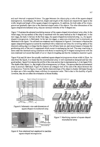
Figure 7 illustrates the adopted machining manner of the square-shaped microchannel array chip. In the
initial stage, the top surface of the chip is machined with the same method as the V-shaped one. In the
next stage, the bank is formed. In the final stage, the square-shaped microchannel array, i.e., the square-
shaped microgrooves, is fabricated. In the last two stages, a same non-rotational tool is employed, as
illustrated in the figure. The utilized non-rotational tool is depicted in Figure 8. First reason is because the
square-shaped microgrooves cannot be machined with a rotational tool since the revolving radius of the
diamond cutting edge is so large that the shapes to be left have been cut, and second reason is because the
positioning error of the tool is suppressed which occurs in exchanging the tool. The array machining is
done under the identical cutting conditions with those in machining the V-shaped microgrooves with the
non-rotational tool except that depth of cut is 1.0(j.m in roughing and that the workpiece material is gold.
Figure 9 (a) and (b) show the actually machined square-shaped microgrooves whose width is 25|i.m. As
seen from the figure, it is found that the microchannel array is well machined as designed and has very
good surface. Figure 9 (c) depicts the profile of the cross section that is represented as A-A in Figure 9 (b).
The depth of the object, i.e., the height of the microgrooves, is 4.95|im. This proves that the microchannel
array is precisely fabricated. Figure 9 (d) shows an enlarged view of the end of the object between the
microgrooves. From the figure, it is seen that the diamond shape of the object is sharply fabricated though
its edges are a little wavelike shape with burr in nanometer order. This is due to the ductility of gold.
However, they do not affect the evaluation of blood fluidity.
Bank Square-shaped microgrooves Non-rotational tool
Figure 6: Schematic view and dimensions of
square-shaped microchannel array
-Shank (b) Square-shaped microgroove machining method
Figure 7: Machining manner of square-shaped
microchannel array
Figure 8: Non-rotational tool employed to machine
square-shaped microgrooves