
Page 187 - Mechatronics for Safety, Security and Dependability in a New Era
P. 187
Ch35-I044963.fm Page 171 Tuesday, August 1, 2006 3:09 PM
Tuesday, August
Page 171
1, 2006
Ch35-I044963.fm
3:09 PM
171
171
(1) (2)
Getting image Image format
from CCD camera conversion A Median filtering L
640pixel
(3)
~
< > Calculation of chamfering
angle and initial position
Diamond file CCD camera
•*sJ "^^Linear actuator
(a) Whole view (b) Enlarged view
Figure 3: Tool station
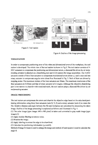
Figure 4: Outline of the image processing
TOOLSTATION
In order to compensate positioning error of the robot and dimensional error of the workpiece, the tool
station is developed. The whole view of the tool station is shown in Fig.3. The tool station consists of 4-
DOF actuators to compensate the positioning and dimensional errors, a diamond file driven by air recip-
rocating actuator is attached as a chamfering tool and CCD-camera for image acquisition. The 4-DOF
actuators consist of three liner actuators to compensate translational errors about x, y and z axes and one
rotary actuator to compensate angular error about 6 as illustrated in Fig. 3. Both of them are driven by
stepping motor. The maximum strokes of the liner actuators are 50mm. The maximum resolutions of the
liner actuators are 0.03mm and that of rotary actuator is 0.1 degree. Although the objective chamfering
part is too narrow to chamfer with rotational tools, the tool station adopt a diamond file driven by ait-
reciprocating actuator.
IMAGE PROCESSING
The tool station can compensate the errors and chamfer the objective edge based on the calculated posi-
tioning information using three liner actuators (axis X, Y, Z) and a rotary actuator (axis A) to rotate the
file. Relative distance and angle between the file and workpiece are calculated by processing the taken
image. Outline of the image processing is explained as follows and illustrated in Fig. 4.
(1) The color image (ppm image: 640 x 480 pixel) is taken and converted to gray scale image (pgm
image).[5]
(2) Apply median filtering to remove noise.
(3) Binarize the image.
(4) Apply labeling to extract the edge to be chamfered.
(5) Calculate the positioning information (y,z and 0).
Method of image bi-linear is used to enlarge the image and method of least squares is used to calculate the
angle 0.