
Page 188 - Mechatronics for Safety, Security and Dependability in a New Era
P. 188
Ch35-I044963.fm Page 172 Tuesday, August 1, 2006 3:09 PM
Ch35-I044963.fm
172
172 Page 172 Tuesday, August 1, 2006 3:09 PM
3 Finger parallel style Table 1 Experimental condition
air grippcr \ Robot arm
Material Cast copper alloy(CAC406)
Dimentions 4>135x2Omm
Width of outlet 5.5,8,11mm
Weight 1kg
Feed speed 0.72mm/s
(a) Initial position
Chamfering width 0.2 - 0.7mm
(c) Experimental
Workpiece Depth of cut 0.5mm
appearance
CCD camera • " • " " H ~* 5.5mm 8mm 11mm
Diamond file
Center point-
(b) Feed direction
(d) Initial position
(a)(b)(c y: 0.78mm (b) y: -0.75mm (c) y: 1.42mm
(a)) y: 0.78mm
1.42mm
y: -0.75mm
(c)
y:
(b)
z: 3.93mm z: 4.80mm z: 2.72mm
z: 3.93mm
z: 4.80mm
z: 2.72mm
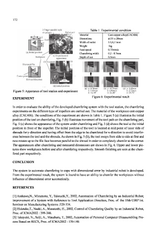
Figure 5: Apperance of tool station and experiment θ: 16.39 θ: 26.20 θ: 25.72
25.72
θ:
16.39
θ: 26.20
θ:
Figure 6: Experimental result
EXPERIMENT
In order to evaluate the ability of the developed chamfering system with the tool station, the chamfering
experiments on the different type of impellers are carried out. The material of the workpiece cast copper
alloy (CAC406). The conditions of the experiment are shown in Table 1. Figure 5 (a) illustrates the initial
position of the tool on chamfering, Fig. 5 (b) illustrates movement of the tool path on the chamfering part,
Fig. 5 (c) shows the appearance of the system under chamfering and Fig. 5 (d) shows the tool at the initial
position in front of the impeller. The initial position of the tool is located at mid point of inner side of
shrouds for y-direction and having offset from the edge to be chamfered for x-direction to avoid interfer-
ence between the tool and the shrouds. As shown in Fig. 5 (b), the tool sways from side to side at first and
next rotates up to the file face becomes parallel to the shroud in order to completely chamfer at the corner.
The appearances after chamfering and measured dimensions are shown in Fig. 6. Upper and lower pic-
tures show workpieces before and after chamfering respectively. Smooth finishing are seen at the cham-
fered part respectively.
CONCLUSION
The system to automate chamfering to cope with dimensional error by industrial robot is developed.
From the experimental result, the system is found to have an ability to chamfer the workpieces without
influence of dimensional error automatically.
REFERENCES
[1] Asakawa,N., Mizumoto, Y., Takeuchi,Y., 2002, Automation of Chamfering by an Industrial Robot;
Improvement of a System with Reference to Tool Application Direction, Proc. of the 35th CIRP Int.
Seminer on Manufacturing Systems :529-534.
[2] Hidetake.T., Naoki, A., Masatoshi, H., 2002, Control of Chamfering Quality by an Industrial Robot,
Proc. of ICMA2002 : 399-346.
[3] Takayuki, N., Seiji, A., Masaharu, T., 2002, Automation of Personal Computer Disassembling Pro-
cess Based on RECS, Proc. of ICMA2002 : 139-146