
Page 186 - Mechatronics for Safety, Security and Dependability in a New Era
P. 186
Ch35-I044963.fm Page 170 Tuesday, August 1, 2006 3:09 PM
Ch35-I044963.fm
170
170 Page 170 Tuesday, August 1, 2006 3:09 PM
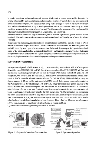
is usually chamfered by human handwork because it is located in narrow space and its dimension is
largely influenced by individual dimensional errors piece by piece. Figure 1 shows the appearance and
dimension of the workpiece. The objective chamfering part is an edge of outlet of the impeller between
front and rear shroud as shown in Fig. 1. The impeller has 6 parts to be chamfered. In the study, y-z plane
is defined as tangent plane on the chamfering part. The dimensional errors occurred in y-z plane and 6,
rotating error around the normal direction on tangent plane are considered.
Since the industrial robot has a large number of degrees of freedom, it provides a good mimic of a human
handwork. Formerly, some studies to automate such contaminated workings by use of industrial robots.
To automate the chamfering, an industrial robot is used to handle and hold the impeller in front of a "tool
station" our own developed in our study. The tool station fixed on a worktable has positioning actuators
and a file driven by air reciprocating actuator as a chamfering tool. To detect positioning and dimensional
errors of the workpiece based on an image of the objective part taken by a camera. The tool station can
compensate the errors and chamfer the objective edge based on the calculated positioning information. In
the article, implementation of the chamfering system and experiments are reported.
SYSTEM CONFIGURATION
The system configuration is illustrated in Fig. 2. Workpiece shapes are defined with 3D-CAD system
(Ricoh Co. Ltd. :DESIGNBASE) on EWS (Sun Microsystems Inc.: UltraSPARC-IT 296MHz). Tool path
for material handling is generated with our own developed CAM system on the EWS and a PC (AT
compatible, OS: FreeBSD) on the basis of CAD data followed by conversion to the robot control com-
mand. A 6-DOF industrial robot (Matsushita Electric Co. Ltd: AW-8060), 2840mm in height, the posi-
tioning accuracy is 0.2mm and the load capacity is 600N, is used. Robot control command generated on
the PC is transferred to the robot through a RS-232-C. A 3-finger parallel style air gripper attached to the
end of the robot hand holds the workpiece. The robot carries the workpiece in front of a CCD camera to
take the image of chamfering part. Positioning and dimensional errors of the workpiece are detected
based on an image of objective part taken by the CCD camera on a PC. The tool station can compensate
the errors and chamfer the objective edge based on the calculated positioning information using three
liner actuators (axis X, Y, Z) and a rotary actuator (axis A) to rotate the file. In the study, the industrial
robot handles the workpieces instead of the chamfering tools. The method has following two advantages.
(1) The workpiece can be chamfered while transferring to reduce lead-time.
(2) No additional transferring/handling equipment is required.
3 Finger parallel style
air gripper
(a) Chamfering part (b) Whole view
6DOF-Robot Tool station
Figure 1: Shapes and dimension of the workpiece Figure 2: System configuration