
Page 335 - Mechatronics for Safety, Security and Dependability in a New Era
P. 335
Ch65-I044963.fm Page 319 Tuesday, August 1, 2006 4:44 PM
1, 2006
4:44 PM
Page 319
Tuesday, August
Ch65-I044963.fm
319
319
10
—o- Coated paper machine direction —on Coated paper machine direction
Coated paper machine direction
Coated paper machine direction
-a- Coated paper thickness direction -a- Coated paper thickness direction
Coated paper thickness direction
Coated paper thickness direction
9 —•- Copy paper machine direction 0.6 —.6 Copy paper machine direction ..; ..X
Copy paper machine direction
Copy paper machine direction
—•- Copy paper thickness direction —on Copy paper thickness direction
Copy paper thickness direction
Copy paper thickness direction
8
0.5
7
t
y n
0.4
e
t
i g 0.4
v 6
i
t n
t
i a
m t
r s
e 5 s 0.3
P o
L
4
0.2
3
0.1
2
1 0
10 20 30 ) 40 50 60 10 20 30 30 40 50 60
40
40
ative humidity (%)
Relative humidity (%)
Relative humidity (%) Relative humidity (%)
a) b)
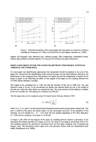
Figure 1: Electrical properties of the coated paper and copy paper as a function of relative
humidity at a frequency of 1 MHz. a) Permittivity b) Loss tangent, Simula et al. (1999).
organic and inorganic ions, adsorbed ions, carboxyl groups, fiber morphology, polarization losses,
rotation and oscillation of polar material, fine structure of cellulose and pulp components.
SIMULATION RESULTS FOR THE COUPLING BETWEEN TWO DIPOLE ANTENNAS
THROUGH THE PAPER REEL
For most paper reel identification applications the transponder should be attached to the core of the
paper reel. This is how the identification of the reel can be done over its whole lifecycle. However, the
performance of the communication link between the reader unit and the transponder is limited due to
losses in paper. In the following the effect of loss tangent of the paper on the coupling between two
915 MHz dipole antennas is studied.
The height of the simulated reel is 1200 mm and the diameter of the reel is 1000 mm. The core
diameter inside is 76 mm. In the simulations one dipole was inserted inside the reel in the middle of
the reel core while the other dipole was outside the reel. The axial position of both dipoles in relation
to the reel was 600 mm. The separation of dipoles was 538 mm.
The free space loss can be evaluated using Friis transmission formula, Balanis (1997)
X
P=P,GG (2)
Am
where is P r, P t, G r and G t are the received and transmitted powers and antenna gains respectively. The
term is called the free space loss factor where X is the wavelength used and r is the separation of the
antennas. For two dipoles (G r - G t — 1.63) with 538 mm antenna separation in 915 MHz frequency
(A = 328 mm) the coupling in free space is -22.05 dB.
In Figure 2, the effect of loss tangent of the paper on coupling between dipoles is presented. In the
simulation the relative permittivity of paper was 2.0. The value of loss tangent varied from 0.05 to 0.5.
The coupling between the antennas is decreased from the free space coupling with increasing loss
tangent value. The simulation results agree well with previous studies with two dimensional layer
model, Keskilammi et al. (2000).