Page 336 - Mechatronics for Safety, Security and Dependability in a New Era
P. 336

Ch65-I044963.fm  Page 320  Tuesday, August 1, 2006  4:44 PM
            Ch65-I044963.fm
               320
               320    Page 320  Tuesday, August  1, 2006  4:44 PM


                                               y
                                       -30
                                                                  0.1
                                       -40 4     '•—^o  •- ^  -  ^. "••*  0.05
                                                                 0.15
                                                                  0.2
                                                                 0.25
                                           s
                                                                  0.3
                                                            "*"• - ^
                                                                  0.4
                                                             N
                                                                  0.5
                                         600  700  800  900  1000  1100  1200
                                                    MHz
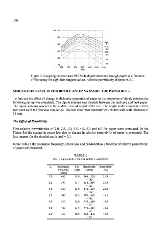
                        Figure 2: Coupling between two 915 MHz dipole antennas through paper as a  function
                        of frequency  for eight loss tangent values. Relative permittivity  of paper is 2.0.
               SIMULATION RESULTS FOR DIPOLE ANTENNA INSIDE THE PAPER REEL

               To find  out the  effect  of change  in dielectric properties  of paper to the properties  of dipole antenna the
               following  set-up was simulated. The dipole antenna was inserted between the reel  core and bulk paper.
               The dipole antenna  was  set in the middle of axial height of the reel. The height and the diameter of the
               reel were as in the previous simulation. The reel core inner diameter was 76 mm with wall thickness of
               16 mm.
               The Effect  of  Permittivity

               First  relative  permittivities  of  2.0,  2.5,  3.0,  3.5,  4.0,  5.0  and  6.0  for  paper  were  simulated.  In  the
               Figure  3a)  the  change  in return  loss  due  to  change  in relative  permittivity  of  paper  is  presented.  The
               loss tangent for the simulations is tanS = 0.1.

               In the Table  1 the resonance frequency,  return loss and bandwidth as a function  of relative permittivity
               of paper are presented.

                                                TABLE 1
                                     SIMULATED RESULTS FOR DTPOLE ANTENNA

                                       Resonance  S11  Bandwidth  Bandwidth
                                       frequency  (dB)  (MHz)   (%)
                                        (MHz)
                                  2.0    630     15.0  568...703  21.4
                                                       =  135
                                  2.5    590     13.7  536...659  20.8
                                                       =  123
                                  3.0    560     13.0  512...624  20.0
                                                       =  112
                                  3.5    540     12.5  492... 595  19.1
                                                       =  103
                                  4.0    510     12.0  474...568  18.4
                                                       = 94
                                  5.0    480     11.5  446...519  15.2
                                                       = 73
                                  6.0    450     10.9  424...478  12.0
                                                       = 54
   331   332   333   334   335   336   337   338   339   340   341