
Page 341 - Mechatronics for Safety, Security and Dependability in a New Era
P. 341
Ch66-I044963.fm Page 325 Thursday, July 27, 2006 12:15 PM
Thursday, July 27, 2006
12:15 PM
Ch66-I044963.fm
Page 325
325
325
2. THE ANTENNA DESIGN
As previously noted, metallic structures near antennas affect their performance in many ways. Placing
a conductive surface near an antenna has advantages and disadvantages. In some cases a metallic plate
near an antenna can act as a reflector causing the directivity to increase. Also a number of antenna
types need a conductive ground plane to function properly. In these cases a metallic surface can be
used to improve the performance of the antenna.
On the other hand, if the antenna does not use a ground plane in its function, the wave radiated by the
antenna is almost totally reflected from the metallic surface since metal is highly conductive. When
electromagnetic wave reflects from metallic surface a 180 degree phase shift occurs (Cheng, 1993).
This reflected wave cancels the incoming wave and therefore the radiation efficiency of the antenna
decreases. These negative effects are strongest when the antenna is very near (for example at a
distance of a couple of millimetres or less) the metallic surface (Raumonen et al, 2003).
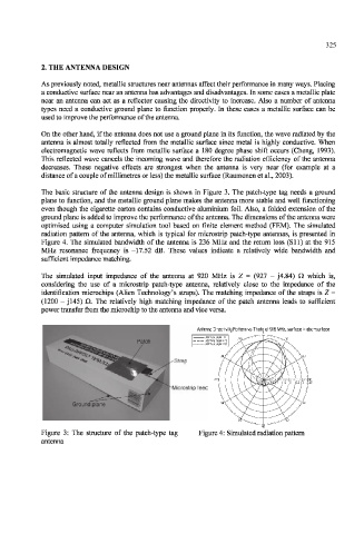
The basic structure of the antenna design is shown in Figure 3. The patch-type tag needs a ground
plane to function, and the metallic ground plane makes the antenna more stable and well functioning
even though the cigarette carton contains conductive aluminium foil. Also, a folded extension of the
ground plane is added to improve the performance of the antenna. The dimensions of the antenna were
optimised using a computer simulation tool based on finite element method (FEM). The simulated
radiation pattern of the antenna, which is typical for microstrip patch-type antennas, is presented in
Figure 4. The simulated bandwidth of the antenna is 236 MHz and the return loss (SI 1) at the 915
MHz resonance frequency is -17.52 dB. These values indicate a relatively wide bandwidth and
sufficient impedance matching.
The simulated input impedance of the antenna at 920 MHz is Z = (927 - J4.84) Q which is,
considering the use of a microstrip patch-type antenna, relatively close to the impedance of the
identification microchips (Alien Technology's straps). The matching impedance of the straps is Z =
(1200 — j 145) Q. The relatively high matching impedance of the patch antenna leads to sufficient
power transfer from the microchip to the antenna and vice versa.
Antenna Directivity Pattern vs Theta at 916 MHz, surface = abc-surface
Strap
Microstrip feed
Figure 3: The structure of the patch-type tag Figure 4: Simulated radiation pattern
antenna