Page 346 - Mechatronics for Safety, Security and Dependability in a New Era
P. 346

Ch67-I044963.fm  Page 330  Tuesday, August 1, 2006  5:54 PM
            Ch67-I044963.fm
               330
               330    Page 330  Tuesday, August  1, 2006  5:54 PM
               current  amplifier  regulates  motor  current,  and  help  to  minimize  the  effects  of  induced  voltage  from
               motor  armatures.  Functionality  of  the  current  amplifier  is  proved  below.  Since  effects  of  induced
               voltage, E(s), to the motor current could be approximated  a linear function,  the transfer  function  of the
               current loop in Figure  l(a) would be defined  in Eqn.  1, and if the integrating gain,  KA, is large enough,
               the effects  of induced voltage, E(s), could be omitted.

                                                                    S                  (1)
                                                       K A                  Vis)
                                                             V(s) -     E(s)
                                                                 R  +aK,
                                                      K  A
                                             Current       T L  (s )     Current   T L  ) (s
                 Current  Current
                                 T L (s )    limiter       -             limiter   -
                 limiter  amplifier  -    K C +   K  A +  1  1   V  ) (s  K C +  K  K A +  K  1  1  1  Θ  ) (s
               V(s)   K  A +  1  I(s)  1  +  -  S  K  D  +  -  S  K  B +  -  R  a  T k  +  J a S  +  -  H V  +  -  S  D  +  -  S  B +  -  R a  T k  +  J a S  S
                   +  S  K B +  R  a  T k  +  J a  S
                     -    -                               E k                α    E k
                           E(s)                   α
                       α        E k
                                                                              G T
                Current control
                Current control  DC Motor           G T
                         (a)                          (b)                 (c)
                                                  (b)
                                                                          (c)
                          (a)
                    Figure  1: Block diagram of (a) the current loop (b) the velocity loop and (c) the position loop
                                                                   Velocity Amp
                               2.0V             2.0V   120       — Velocity Am  30  Velocity Amp
                 400              400
                )              3.5V  )          3.5V               Integrating      Integrating
                a I " d  300   7.0V  d  a  300  7.0V   v  (        Proportion  v  (  20  Proportion
                s  /              s  /                 )  90              n
                                                                        )
                r                 r                    e  60       Current Limit  e  Current Limit
                (              14.0V  (         14.0V
                                                       d                d
                y  200            y  200  2
                t                 t 200                u                u
                i                 i                    t  i  30         t  i  10
                o 2 c             c                    l                l
                l                 e I o  l             p                p  0 n\
                e  100            100                  m  0             m
                V                 V                    A                A
                  0                0                   -30 0  0.02  0.04  0.06  0.08  0.1
                                                                               0.04
                                                                            0.02
                                                                                    0.08
                •I  100 -                                                 0  0.02  0.04  0.06  0.08  0.1 0
                                                                                 0.06
                  0  0.02  0.04  0.06  0.08  0.1  0  0.02  0.04  0.06  0.08  0.1  -60  -10
                                                              Time (s) s)
                        Time (s)         Time (s)             Time(     -10    Time (s) )
                                                                               Time( s
                                                                        (b) with
               (a) without anti-windup (b) with
                                                                              anti-windup
                                       anti-windup
                                                      (a) without anti-windup
                (a) without anti-windup (b) with anti-windup      (a) without anti-windup  (b) with anti-windup
               Figure 2: Step responses of the velocity loop  Figure 3: Simulation results (14V step command)
                  3
                  10                20               )  20             )  40
                               2.0V             2.0V  v  (       Input  v  (      Input
                                                                          20
                               3.5V  0          3.5V  e  d       Cur.Limit.Out  e  d  Cur.Limit.Out
                               7.0V             7.0V  u  t  0    Vel.Amp.Out  u  t  0  Vel.Amp.Out
                                                     i l               i l
                  2            14.0V            14.0V  p               p
                  10               -20                                 -20
                                   )                 m                 m
                 e                 g                 A                 A
                 d                 e                 -20               -40
                 u                 d
                 t                 (                  0  0.02  0.04  0.06  0.08  0.1  0.1  0.11  0.12  0.13  0.14  0.15
                 i l               e  -40
                 p                 s
                 m                 a  h              )  s  200        )  s  100
                 A  1              P                 /                /
                  10               -60               d           Motor Vel.  d     Motor Vel.
                                                     a                a
                                                     r                r
                                                     (                (
                                                        y                y
                                   -80               t  i  0          t  i  0
                                                     c                c
                                                     o                o
                  0                                  l  e             l  e
                  10               -100
                   0   1    2   3    0   1    2   3  V  -200          V  -100
                  10   10  10   10  10   10  10   10  0  0.02  0.04  0.06  0.08  0.1  0.1  0.11  0.12  0.13  0.14  0.15
                       Frquency (Hz)     Frquency (Hz)      Time (s)          Time (s)
                       Frquency(Hz)
                    (a) Amplitude
                                                                            (d)40Hz
                                                          (c) 20Hz
                                        (b) Phase
                    (a) Amplitude       (b) Phase            (c) 20Hz            (d) 40Hz
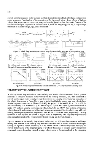
                      Figure 4: Frequency responses and Simulation results (7V P. P input) of the velocity loop
               VELOCITY CONTROL WITH CURRENT LOOP
               A  velocity  control  loop  maintains  a  motor  velocity  run  by  the  velocity  command  from  a  position
               amplifier.  It  compares  measured  motor  velocity  to  the  velocity  command,  and,  then,  commands  a
               current  loop to  adjust  motor  velocity  in order to minimize  the  velocity  error. Numerical  simulation  of
               the  velocity  loop  shown  in  Figure  1 (b) is used to  study the  effect  of a current loop  on a velocity  loop.
               Simulation parameters are set as follows: K c  is 800, K D is 6, a  is 2, K A is 4000, K B is  1, R a is 8.7fi,  k F ,
                                                   5
                                                        2
               is 0.187V/(rad/s),  k T is 0.188Nm/A,  J a is 5.59xl0" Kg.m ,  T G is 0.0668V/(rad/s),  the current  limiter  is
               set to  ±8V,  and  step  velocity  commands  are  2.0V,  3.5V,  7.0V  and  14.0V.  Two  systems, which  are a
               velocity loop with anti-windup  and without anti-windup, are simulated. For the velocity loop with anti-
               windup,  the integrating  limit  and proportional  limit  are  set  at ±10V  and ±15V, respectively.  The  step
               responses  of  both  systems  are  shown  in  Figure  2  and  3  respectively.  The  frequency  responses  and
               some simulation results of the velocity  loop with anti-windup are shown in Figure 4.
               Figure  2  shows  that  the  velocity  loop  without  anti-windup  has  high  overshoot  response  and  longer
               settling time than that of the velocity  loop with anti-windup because  of current  saturation  and integral
               windup.  In  regard  to  current  saturation,  it  is  the  current  limiter  in  the  velocity  loop;  however,  the
               current  limiter  is  one  of  the  important  parts  of  a  velocity  loop  since  it prevents  a  servo  motor  from
               overloaded  current.  Regarding  integral  windup,  velocity  error  is  fast  accumulated  in  the  integrating
   341   342   343   344   345   346   347   348   349   350   351