
Page 348 - Mechatronics for Safety, Security and Dependability in a New Era
P. 348
Ch67-I044963.fm Page 332 Tuesday, August 1, 2006 5:54 PM
Ch67-I044963.fm
332
332 Page 332 Tuesday, August 1, 2006 5:54 PM
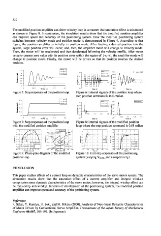
The modified position amplifier can drive velocity loop in a manner that saturation effect is minimized
as shown in Figure 8. In conclusion, the simulation results show that the modified position amplifier
can improve speed and accuracy of the positioning system. How the modified positioning system
switches between velocity mode and position mode is demonstrated in Figure 9. According to that
figure, the position amplifier is initially in position mode. After feeding a desired position into the
system, large position error will occur, and, then, the amplifier mode will change to velocity mode.
Then, the motor will be accelerated and then decelerated following the velocity profile. After motor
velocity crosses zero value with its position error within the region of [-e,+s], the amplifier mode will
change to position mode. Finally, the motor will be driven so that its position reaches the desired
position.
0.04
1.2
0.16 Pos.Amp 150 Motor Vel.
) 1 30
d 0.63 Vel.Amp
a ) s 100
r 0.8 ) Cur.Limit /
( v 15 d
n ( a 50
o i t 0.6 e d r (
a t 0.4 u t i 0 y t i 0
o l p c
R 0 0.05 0.1 0.15 0.2 o -50 0 0.05 0.1 0.15 0.2
0.2 m l e
A -15 V
0 -100
0
1
0 0 0.05 5 0.1 0.15 5 0.2 2
° Time (s) ) ° °" -30 Time (s) -150 Time (s)
Ti&l( S
Figure 5: Step responses of the position loop Figure 6: Internal signals of the position loop where
step position command is 0.63 radian.
0.04
0.04
0.8
0.16
0.16 Pos.Amp 80 80 " | 0 Motor Vel.
Mot orVel.
) 30 0 3 ' A
d r f a 0.6 " " 0.63 Vel.Amp )
Vel Amp
0.6
Cui Limi
( v "p 2 ) 20 0 • Cur.Limit s / d 60
n ( t ft
a
e
o 0.4 t 1 1 r 40
i 0.4 - - d 10 • ! ( « •
t u 10
a y
t i l i
o rKii c 20
R 0.2 - - p 0 o
0.2
m 0.2 l e
0
0
0.05
A 0 1 0.05 0.1 1 0.15 15 0.2 V 0
0 -10 j 10 •
0.
0.15
0.2
1
0 0 0.05 5 0.1 0.15 5 0.2 2 -20 " 0 0.05 1 0.1 0.1 0.15 0.2
0
-20
° Time (s) > ° °" -20 Time (s) Time (s)
Tifii (s
Time(s)
Figure 7: Step responses of the position loop Figure 8: Internal signals of the modified position
with the modified position amplifier 0.16 __. is 0.63 radian
loop where the step position command
5 2 Vel.Mod Profile 1.01
Vel.Mod Profile
1 Pos.Mod Profile 1.2
4 1.5 1.005 1 1 1 1
Switching point 0.63 1
3 from Vel.Mod 0.04 ::: 1
) 2 -- ) v 1 to Pos.Mod ) )
v ( d d
( 2 0.995 — 1 — [ - - •
a 0.8 a r yi
e e r r (
d d u o i "^-hi 4
(
u 0.5 n n
t 1 t i l o = ^ 6 o 0.99
i l p i t 0.6 i t 1
p i 8 o % "-
i
m 0 -1 -4 4 L m s 10 s 0.985 0.005
A Vel.Mod Profile A 0 P 0.4 P 0.010
-1 Pos.Mod Profile -0.005it 1 1 1 0.98 —SS
0.16 1 11 0.015
Velocity profile -0.5 0.2 1
-2 0.63 Velocity Control 0.975 0.020
ft.M 0.04 ; ;
-3 -1 1 Position Control 0 ! ! ! 0.97
I,
-0.2 -0.1 0 0.1 0.2 0.3 0.4 0.5 0.6 -0.015 -0.01 0 0.005 0.01 0.015 0 0.02 0.04 0.06 0.08 0.1 0.01 0.015 0.02 0.025 0.03 0.035 0.04
Position error (rad) Position error (rad) Time (s) Time (s)
Figure 9: Phase-plan diagram of the modified Figure 10: Unit step responses of the positioning
position loop system (varying VH(NL) and e respectively)
CONCLUSION
This paper studies effects of a current loop on dynamic characteristics of the servo motor system. The
simulation results show that the saturation effect of a current amplifier and integral wind-up
complicates some dynamic characteristics of the servo motor; however, the integral windup effect can
be reduced by anti-windup. In terms of development of the positioning system, the modified position
amplifier can improve speed and accuracy of the positioning system.
Reference
F. Sakai, Y. Kamiya, H. Seki, and M. Hikizu (2000). Analysis of Non-linear Dynamic Characteristics
of Motor Driven by Conventional Servo Amplifier. Transactions of the Japan Society of Mechanical
Engineers 66:667, 189-195. (In Japanese)