Page 350 - Mechatronics for Safety, Security and Dependability in a New Era
P. 350

Ch68-I044963.fm  Page 334  Tuesday, August 1, 2006  8:30 PM
            Ch68-I044963.fm
               334
               334    Page 334  Tuesday, August  1, 2006  8:30 PM
               that the on/off  valve has a simple configuration  and, furthermore,  can be a logical  interface  between a
               computer  and  hydraulic  systems.  Hence,  a  low  cost  and  highly  reliable  system  may  be  developed,
               under the recent condition that the systems are equipped with computers.
               In the  present  study,  we propose  an  active  control  hydro-pneumatic  suspension  system  composed  of
               high speed on/off  solenoid valves which are driven in a PWM (Pulse  Width Modulation)  digital mode.
               In order to realize a robust control  system  even when  measurement  errors exist, we adopted  a preview
               control  method  equipped  with  an  ADF  (adaptive  digital  filter).  The  experiment  was  performed  by
               using a bench  system which physically  simulates  induced vibrations  from  the road  and  also  simulates
               the  body  mass  of  an automobile.  The results obtained  from  the  system  using  preview  control  with  an
               ADF were compared with those obtained  from  a system using a conventional sky-hook control.

               CONSTITUTION  OF THE ACTIVE SUSPENSION   SYSTEM

                                       p p
                                        s s
                                                       M M b b
                                                       Mb
                                    Valve-1
                                    Va l v e - 1                   x b x b
                                                    at
                                                  Ac
                                                  Actuator
                                                     or
                                                   t
                                                    u
                                                             p g p g
                                                                   x g x g
                                                       p p a1  p p a2
                                                             a2
                                                        a1
                                                              rin
                                                             p
                                                           G Gas spring g
                                                           a
                                                            s s
                                                       M M w w     x x
                                                       Mw
                                       Valve-2
                                       V al ve- 2                   w w
                                                    K t K t
                                                                   x x r r
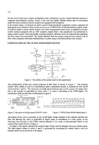
                              Figure  1: The outline of the system used for the experiment
               The  configuration  of  the  new  system  proposed  in  this  study  is  shown  in  Figure  1.  The  pressure
               control  valve,  which  is  used  in  a  conventional  active  suspension  system,  is  replaced  by  two  on/off
               valves (valves  1 and 2).  The valves are of a high-speed  solenoid type. In this  system, the  supply  flow
               rate  to  the  cylinder  is  controlled  by  either  valve  1 or  valve  2  according  to  the  PWM-signal.  The
               constitution of the on/off valve is illustrated  in Figure 2.
                         o pump or reservoir
                        To pump or reservoir
                                          Poppet valve
                                          Poppet valve
                                                      u u
                                                    a
                                                      a
                                                     o
                                                    e t
                                                    g
                                                       V
                                                 na
                                                 g
                                                  l
                                                   v
                                                   o
                                                Si Signal voltage to Valve1 e 1
                                                   t
                                                       lv
                                                   l
                                                      a
                                                       V
                                                       lv
                                                     o
                                                 na
                                                  l
                                                   v
                 Linear                   Spring  Si Signal voltage to Valve2 e 2
                                          Spring
                                                 g
                                                    a
                                                    g
                                                    e t
                                                   o
                                                   l
                                                   t
                 solenoid      To cylinder
                                 cylinder
               Figure 2: Structure of a high-speed ON/OFF valve  Figure 3: PWM (Pulse-Width-Modulation  )
               The  poppet  in the  valve  is  actuated  by  the  on/off  input  voltage  applied  to  the  solenoid  and  thus  the
               flow  rate  through  the  valve  is  controlled  in  digital  mode  in  accordance  to  a  duty  signal.  Tn  the
               following,  the  principle  of  the  PWM  method  adopted  in  this  study  is  demonstrated  based  on  the
               experimental results shown in Figure 3.
                 In Figure 3, the signal u denotes the control input (=Duty)  and the triangle waves are carrier waves.
               The  input  signal  voltage  to  valves  1 and  2  is  generated  by  comparing  the  control  input  u  with  the
               triangle carrier waves as shown in the  figure.
   345   346   347   348   349   350   351   352   353   354   355