Page 351 - Mechatronics for Safety, Security and Dependability in a New Era
P. 351

Ch68-I044963.fm  Page 335  Tuesday, August 1, 2006  8:30 PM
                            Tuesday, August
                                           8:30 PM
                                      1, 2006
                      Page 335
            Ch68-I044963.fm
                                                                                          335
                                                                                          335
                          40
                                                           50


                        .'"•  -40

                                           = lOMPa                        p s =10MPa
                                          p s
                             /           % = 50Hz                         f c = 50Hz
                                                          -50  -
                            -100       0        +100         -100       0        + 100
                                                    O//
                                                  ut ;
                                (a)  Without compensation  ® }  r °l  (b)  With compensation  Duty I
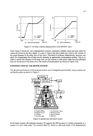
                                Figure 4: The Duty-velocity  characteristics of an ON/OFF valve
                  Next, Figure 4  shows the valve  characteristics  between  suspension  cylinder  speed  and  duty when the
                  valves are driven by the  duty  signal. It  is  seen  in Figure  4(a) that a dead  zone exists  in the vicinity  of
                  the  origin  because  of the  delay time  of the valve. This  kind  of nonlinear  characteristic,  however,  can
                  easily  be compensated  into a  linear  one  by adopting  an appropriate  compensation  method.  That  is, in
                  order to cancel  the  influence  of the  dead zone, we  can  impose  a wider pulse width  than  the  estimated
                  Duty by the amount of the delay time. The results of compensation are shown in Figure 4 (b).
                  CONSTRUCTION   OF THE BENCH  SYSTEM

                  The dynamic performance  of the proposed  system was investigated  experimentally  using a quarter-car
                  test bench system as shown in Figure 5.

                                              Computer
                                              Co m p u t e r
                                                          8 8
                                                     o
                                         A/
                                         A/D conv. .  D/A conv. .  Amp. .
                                             v
                                                       v
                                             n
                                            o
                                                      n
                                                                Am
                                                                  p
                                                  D/
                                          D c
                                                   A c
                                          Amp. .
                                             p
                                          Am
                                                            1 1
                                               2 2
                                              3 3
                                                                   n
                                                                   u
                                                                  e
                                                               Va
                                                                 v
                                                                 l
                                                               Valve unit i t
                                             4 4
                                                             5 5
                                           3 3
                                         6 6
                                         7 7
                                                        2 2. Acceleration
                                                 0k
                                                   g)
                                                                  senso
                                                                  s
                                                                n
                                                                    or
                                                                    s
                                                                  en
                                                                o
                                                           ccel
                                                          A
                                                         .
                                                               i
                                                               t
                                                             era
                                              h
                                               (
                                         1. Weight (200kg)
                                             g
                                           W
                                            e
                                            i
                                                20
                                         1. 1. Weight t   (200kg)  2. Acceleration sensor r
                                              o
                                                        4. Pressure sensor
                                         3 3. Position sensor
                                         3. Position sensor          4. Pressure sensor
                                              n
                                          . P
                                             ti
                                                 n
                                            s
                                             i
                                                  o
                                                   r
                                                s
                                                 s
                                           o


                                                e
                                                                h
                                                                  l

                                                           lle
                                                                 e
                                                               (
                                           c
                                                             r
                                            t
                                                              W
                                                           o

                                              t
                                                                e
                                               o

                                               r

                                          . A
                                             u

                                                          R
                                         5. Actuator                       6. Roller (Wheel) )
                                                         .
                                             a
                                         5 5. Actuator
                                                        6 6. Roller (Wheel)
                                         7. Eccentric disk
                                         7 7. Eccentric c   d disk k  8. 8.DS1104
                                              t
                                                        8. DS1104
                                                          D
                                                 i
                                                  s
                                              ri
                                           ccen
                                           E
                                          .
                                                           S
                                                            11
                                                             04
                                         Figure  5: Quarter-car test bench system
                  Tn the bench  system, the hydraulic  actuator  (5)  supports  the  200 kg  mass  (1)  which  corresponds  to a
                  quarter  of  a car's  body  mass. The  eccentric  disk  (7), which  is  a physical  model  of the  displacement
   346   347   348   349   350   351   352   353   354   355   356