
Page 356 - Mechatronics for Safety, Security and Dependability in a New Era
P. 356
Ch69-I044963.fm Page 340 Friday, July 28, 2006 1:50 PM
Ch69-I044963.fm
340
340 Page 340 Friday, July 28,2006 1:50 PM
APPLICATION
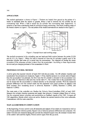
The studied application is shown in Figure 1. Timbers are loaded from ground to the palette of a
loader or unloaded from the palette to ground. When a load is lowered the lift cylinder has an
overrunning load. When a load is raised the jib cylinder has overrunning load, respectively. A
question is can these overrunning loads be utilized in energy recovering. The whole working range of
the boom is shown in Figure 1. The end points of the studied movements are marked to the Figure 1.
£OINT 1 (6,45,1.4)
Telescope Cylinder POINT 2 [3,2.0]
_, 6
Lift Cylinder 2
/
i
: ° /
J
I \i
3 -2
...4^
-4 — - — - — -
Figure 1. Example boom and working range
The studied movements in the unloading case are back-and-forth motion between the points (3,2,0)
and (6,-3.5,1.4), Figure 1. When the load is lowered oil from the lift cylinder is partly used in the
telescope cylinder and extra oil is stored into the accumulator. The required oil during the return
movement of the telescope cylinder is taken from the accumulator. According to these requirements
the size and pre-charging pressure of the accumulator is fixed.
PROPOSED CONTROL METHOD
A driver gives the required velocity of each DOF with his joy-sticks. The lift cylinder chamber and
accumulator line pressures are measured, Figure 1. If the chamber pressure is a certain amount higher
than the accumulator line pressure, the flow from the lift cylinder is directed to the accumulator line
via the valve V2 otherwise to the tank line via the valve VI. The volume flow to the accumulator line
can be stored into the accumulator or utilized directly in the telescope cylinder. With the measured
pressure difference over the control notch and the estimated valve spool position an adaptive and
fairly accurate flow measuring device is achieved, Kannisto 1 (2002), Kannisto 2 (2002), and
Kannisto 3 (2002).
The main tasks of the controller are: Realize the Velocity State-Controllers (VSC) of each DOF.
Measure the cylinder chamber pressures and supply line pressure. Compute volume flows of valves.
Use the computed piston velocities and accelerations as feedback signals of the VSC. Compute all
VSC-algorithms. Decide which valves are active. Realize the current controls of the valve solenoids.
Communicate with the main controller.
MAIN ALGORITHMS IN COMPUTATION
At the beginning of every control cycle all pressures and outputs of joy-sticks are measured as well as
on/off-type position reference points. Square roots of absolute pressure differences are computed. The
actual velocities are estimated taking into account the estimated square root, the nominal volume flow
of the control valve and the slightly filtered control signal from the joy-stick.