
Page 360 - Mechatronics for Safety, Security and Dependability in a New Era
P. 360
Ch70-I044963.fm Page 344 Friday, July 28, 2006 1:50 PM
Ch70-I044963.fm
344
344 Page 344 Friday, July 28,2006 1:50 PM
M(s) F(s) -A
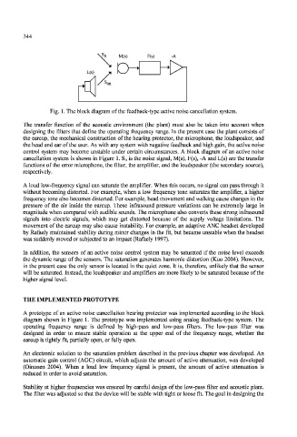
Fig. 1. The block diagram of the feedback-type active noise cancellation system.
The transfer function of the acoustic environment (the plant) must also be taken into account when
designing the filters that define the operating frequency range. In the present case the plant consists of
the earcup, the mechanical construction of the hearing protector, the microphone, the loudspeaker, and
the head and ear of the user. As with any system with negative feedback and high gain, the active noise
control system may become unstable under certain circumstances. A block diagram of an active noise
cancellation system is shown in Figure 1. S n is the noise signal, M(s), F(s), -A and L(s) are the transfer
functions of the error microphone, the filter, the amplifier, and the loudspeaker (the secondary source),
respectively.
A loud low-frequency signal can saturate the amplifier. When this occurs, no signal can pass through it
without becoming distorted. For example, when a low frequency tone saturates the amplifier, a higher
frequency tone also becomes distorted. For example, head movement and walking cause changes in the
pressure of the air inside the earcup. These infrasound pressure variations can be extremely large in
magnitude when compared with audible sounds. The microphone also converts these strong infrasound
signals into electric signals, which may get distorted because of the supply voltage limitations. The
movement of the earcup may also cause instability. For example, an adaptive ANC headset developed
by Rafaely maintained stability during minor changes in the fit, but became unstable when the headset
was suddenly moved or subjected to an impact (Rafaely 1997).
In addition, the sensors of an active noise control system may be saturated if the noise level exceeds
the dynamic range of the sensors. The saturation generates harmonic distortion (Kuo 2004). However,
in the present case the only sensor is located in the quiet zone. Tt is, therefore, unlikely that the sensor
will be saturated. Instead, the loudspeaker and amplifiers are more likely to be saturated because of the
higher signal level.
THE IMPLEMENTED PROTOTYPE
A prototype of an active noise cancellation hearing protector was implemented according to the block
diagram shown in Figure 1. The prototype was implemented using analog feedback-type system. The
operating frequency range is defined by high-pass and low-pass filters. The low-pass filter was
designed in order to ensure stable operation at the upper end of the frequency range, whether the
earcup is tightly fit, partially open, or fully open.
An electronic solution to the saturation problem described in the previous chapter was developed. An
automatic gain control (AGC) circuit, which adjusts the amount of active attenuation, was developed
(Oinonen 2004). When a loud low frequency signal is present, the amount of active attenuation is
reduced in order to avoid saturation.
Stability at higher frequencies was ensured by careful design of the low-pass filter and acoustic plant.
The filter was adjusted so that the device will be stable with tight or loose fit. The goal in designing the