
Page 357 - Mechatronics for Safety, Security and Dependability in a New Era
P. 357
Ch69-I044963.fm Page 341 Friday, July 28, 2006 1:50 PM
Friday, July 28,2006
1:50 PM
Page 341
Ch69-I044963.fm
341
341
The velocity errors between the reference signal (from joy-stick) and the velocity feedbacks
(estimated velocities) are computed and set inputs to the VSCs. The gains of the VSCs (integral
gains, velocity and acceleration feedback gains) are tuned for smooth dynamic behavior. The output
of the lift cylinder VSC is then handled by the valve switching logic between valves VI and V2.
When the pressure difference is lower than the lower limit of the pressure hysteresis the flow is
directed to the tank line via the valve VI. When the pressure difference is higher than the lower limit
but lower than the higher limit of the pressure hysteresis the valve VI is still operated and the flow is
directed to the tank line. Mostly the flow through the valve V2, in the cases of overrunning loads, is
used in the telescope cylinder, but also partly to load the accumulator. In order to get roughly
approximation for the orientation of the boom the positions of the pistons are computed by integrating
the estimated velocities of the pistons. Three on/off switches are used in each DOF as reference
points to improve the position computation accuracy. The forward kinematics of the boom is then
used to compute finally the orientation of the boom.
SIMULATION RESULTS
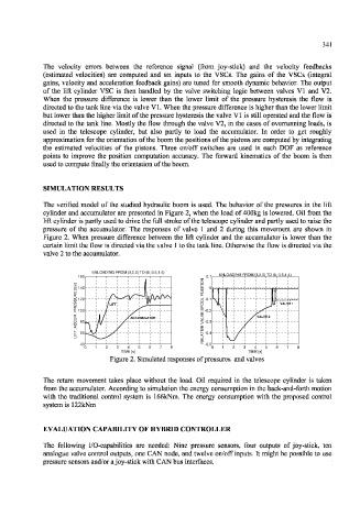
The verified model of the studied hydraulic boom is used. The behavior of the pressures in the lift
cylinder and accumulator are presented in Figure 2, when the load of 400kg is lowered. Oil from the
lift cylinder is partly used to drive the full stroke of the telescope cylinder and partly used to raise the
pressure of the accumulator. The responses of valve 1 and 2 during this movement are shown in
Figure 2. When pressure difference between the lift cylinder and the accumulator is lower than the
certain limit the flow is directed via the valve 1 to the tank line. Otherwise the flow is directed via the
valve 2 to the accumulator.
UNLOADING FROM (3,2,0) TO (6 -3.5,1 4
UNLOADING FROM (3,2,0) TO (6,-3.5,1.4) )
UNLOAD ING FROM (3,2,0) TO (6 -3.5,1.4)
160 8 N O 0.1 UNLOADING FROM (3,2,0) TO (6,-3.5,1.4)
S U RE [bar] r a b [ E R U S 140 1 1 / \ V*"" \ f I T I S O P L O O -0.1 0 1 VALVE 1
]
120 I
LIFT, ACCUM. PRESS E R P . M U C C A , T 100 I LIFT / / ACCUMUL MULA OR 0 P S -0. -0.2 2 \ / / VALVE 2 2
LIFT
VALV
E
V
ACCUMULATOR
L
A
-0.3
-0.3
80
V
E
40 D g 8 8
V
I
T
-0.4
60
F
I
L
L
E
R 11 1
-0.5
-0.5
0 0 1 1 2 2 3 3 4 4 5 5 6 7 8 = A -0.4 0 1 2 3 3 4 4 5 6 3 7 ? 8 8
TIME [s]
TIME [s]
TIME [s] TIME [s]
Figure 2. Simulated responses of pressures and valves
The return movement takes place without the load. Oil required in the telescope cylinder is taken
from the accumulator. According to simulation the energy consumption in the back-and-forth motion
with the traditional control system is 166kNm. The energy consumption with the proposed control
system is 122kNm
EVALUATION CAPABILITY OF HYBRID CONTROLLER
The following I/O-capabilities are needed: Nine pressure sensors, four outputs of joy-stick, ten
analogue valve control outputs, one CAN node, and twelve on/off inputs. It might be possible to use
pressure sensors and/or a joy-stick with CAN bus interfaces.