
Page 382 - Mechatronics for Safety, Security and Dependability in a New Era
P. 382
Ch74-I044963.fm Page 366 Tuesday, August 1, 2006 9:45 PM
Ch74-I044963.fm
366
366 Page 366 Tuesday, August 1, 2006 9:45 PM
higher productive manufacturing system, which enables maximum capacity of 5-axis machining
center's productivity.
Post measurement systems using some sensor and Cs control on machine tools have been developed
for confirming shape and dimension. In these systems, measurements are carried on the machine tool's
table, so work piece loading for the measurement is not required. There are two proposed measuring
sensors for On-machine work piece measurement. One is a contact triggering touch probe with a
simple mechanism called 3-D touch probe. The other is non-contact laser displacement sensor with
sophisticated electronic optical device. 3-D touch probe is commonly used in On-machine
measurement, and On-machine measurement with correcting process is already proposed [1]. However,
the proposed system is only used for dimensional measurement and not suitable for free form shape
measurement such as die/mold shape. On the other hand, laser displacement sensor has a possibility
for a free form shape because it has an ability that acquire large amount of points at high speed.
Nakagawa showed the advantage of laser displacement sensor on free curved surface measurement [2].
In this report, On-machine measurement of a mold which had free curved surfaces was carried on the
3-axis controlled machining center using laser displacement sensor. When normal vector of
measurement surface is inclined to laser, error arises. Moreover, the angle between laser and normal
vector is larger, the measurement is impossible. In this case, the measurement can be done by giving
two additional degrees of freedom to the laser displacement sensor. The additional degree of freedom
is realized by adding rotary axis of 5-axis machining center. On the 5-axis machining center, laser
always radiate perpendicularly to the measurement surface.
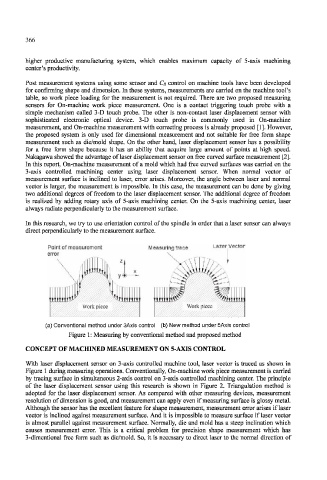
In this research, we try to use orientation control of the spindle in order that a laser sensor can always
direct perpendicularly to the measurement surface.
Point of measurement Measuring trace Lazer Vector
error
(a) Conventional method under 3Axis control (b) New method under 5Axis control
Figure 1: Measuring by conventional method and proposed method
CONCEPT OF MACHINED MEASUREMENT ON 5-AXIS CONTROL
With laser displacement sensor on 3-axis controlled machine tool, laser vector is traced as shown in
Figure 1 during measuring operations. Conventionally, On-machine work piece measurement is carried
by tracing surface in simultaneous 2-axis control on 3-axis controlled machining center. The principle
of the laser displacement sensor using this research is shown in Figure 2. Triangulation method is
adopted for the laser displacement sensor. As compared with other measuring devices, measurement
resolution of dimension is good, and measurement can apply even if measuring surface is glossy metal.
Although the sensor has the excellent feature for shape measurement, measurement error arises if laser
vector is inclined against measurement surface. And it is impossible to measure surface if laser vector
is almost parallel against measurement surface. Normally, die and mold has a steep inclination which
causes measurement error. This is a critical problem for precision shape measurement which has
3-dimentional free form such as die/mold. So, it is necessary to direct laser to the normal direction of