
Page 383 - Mechatronics for Safety, Security and Dependability in a New Era
P. 383
Ch74-I044963.fm Page 367 Tuesday, August 1, 2006 9:45 PM
Tuesday, August 1, 2006
Page 367
9:45 PM
Ch74-I044963.fm
367
367
the surface as correctly as possible for executing surface measurement with high accuracy. Then, as
mentioned above, we tiy to use additional two rotary axes of 5-axis machining center for surface
measurement. Laser vector is traced by using orientation control of the spindle on five axis machining
center as shown in Figure l(b). With this method, not only measurement error is reduced but also all
surface measurement in particular die of convex is enabled. For these reason, On-machine work piece
measurement on 5-axis controlled machining center has an advantage for work piece measurement
after machining.
Circuit of signal amplification
Semiconductor laser
Receive light element
Object lens
Receive light lens
Work piece J
Displacement 1 ^ ^ f ^ ^ Standard position
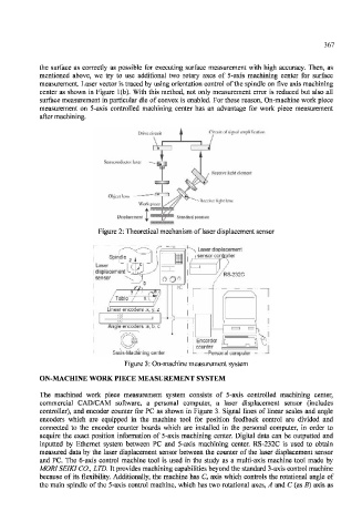
Figure 2: Theoretical mechanism of laser displacement sensor
I Spindle
: Laser
L
| displacement
: sensor
I
i J
L- — 5axis-Machining center — — L_ —Personal computer
Figure 3: On-machine measurement system
ON-MACHINE WORK PIECE MEASUREMENT SYSTEM
The machined work piece measurement system consists of 5-axis controlled machining center,
commercial CAD/CAM software, a personal computer, a laser displacement sensor (includes
controller), and encoder counter for PC as shown in Figure 3. Signal lines of linear scales and angle
encoders which are equipped in the machine tool for position feedback control are divided and
connected to the encoder counter boards which are installed in the personal computer, in order to
acquire the exact position information of 5-axis machining center. Digital data can be outputted and
inputted by Ethernet system between PC and 5-axis machining center. RS-232C is used to obtain
measured data by the laser displacement sensor between the counter of the laser displacement sensor
and PC. The 6-axis control machine tool is used in the study as a multi-axis machine tool made by
MORISEIKI CO., LTD. It provides machining capabilities beyond the standard 3-axis control machine
because of its flexibility. Additionally, the machine has C s axis which controls the rotational angle of
the main spindle of the 5-axis control machine, which has two rotational axes, A and C (as B) axis as