
Page 388 - Mechatronics for Safety, Security and Dependability in a New Era
P. 388
Ch75-I044963.fm Page 372 Tuesday, August 1, 2006 5:58 PM
Ch75-I044963.fm
372
372 Page 372 Tuesday, August 1, 2006 5:58 PM
The sequential two points method (STPM) was developed to evaluate the straight form error of
machine tools. By this method it is possible to identify both error forms for the tool post and the
machined part by a single feed traverse of the tool post in terms of simple algorithm for the data
(Tozawa et al. (1982), Tanaka & Sato (1986)). The method has advantages in that any standard of
specific straightness is not required, the algorithm is simple, repetiive measurement accuracy is high,
and the result is stable even under vibration environment.
In this investigation, the following targets are set to evaluate the straightness error movement of the
probe of the CMM, and consequently its error space, which makes it possible to compensate the error
for the work space and to improve performance in accuracy:
1. Identify the straightness error motion of the probe in the CMM,
2. Identify the planelike error form which is composed of a bundle of the straightness error motions
for the objective plate due to term 1,
3. Identify the 3D error space and develop a compensation method for 3 axes.
EXPERIMENTAL FACILITIES
Principle of STPM
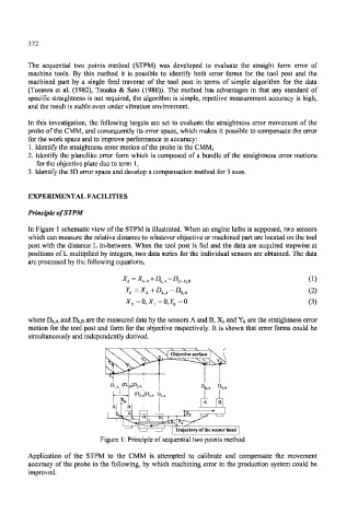
In Figure 1 schematic view of the STPM is illustrated. When an engine lathe is supposed, two sensors
which can measure the relative distance to whatever objective or machined part are located on the tool
post with the distance L in-between. When the tool post is fed and the data are acquired stepwise at
positions of L multiplied by integers, two data series for the individual sensors are obtained. The data
are processed by the following equations,
X/, - -^st-1 + D tA D {k_ i)B (1)
(2)
Y k=X k+D kA-D 0J!
X 0=Q,X }=0,Y 0=Q (3)
where D^A and D^B are the measured data by the sensors A and B, X^ and Yt are the straightness error
motion for the tool post and form for the objective respectively. It is shown that error forms could be
simultaneously and independently derived.
Trajectory of the sensor head
Figure 1: Principle of sequential two points method
Application of the STPM to the CMM is attempted to calibrate and compensate the movement
accuracy of the probe in the following, by which machining error in the production system could be
improved.